Ultrasound measurement assembly for multidirectional measurement

A technology of ultrasonic measurement and components, applied in the direction of measuring devices, radio wave measurement systems, using re-radiation, etc., to achieve the effect of reduced delay and high angular resolution

Inactive Publication Date: 2014-05-14
KONINKLJIJKE PHILIPS NV
View PDF6 Cites 58 Cited by
  • Summary
  • Abstract
  • Description
  • Claims
  • Application Information

AI Technical Summary

Problems solved by technology

The disadvantage of this method is the delay when scanning a large angular spread with a narrow beam, since the beam has to be steered in small steps through the entire angular spread where individual measurements are made
Therefore, this standard raster scan method must trade latency for angular resolution

Method used


Image

  • Ultrasound measurement assembly for multidirectional measurement
  • Ultrasound measurement assembly for multidirectional measurement
  • Ultrasound measurement assembly for multidirectional measurement

Examples


Embodiment Construction

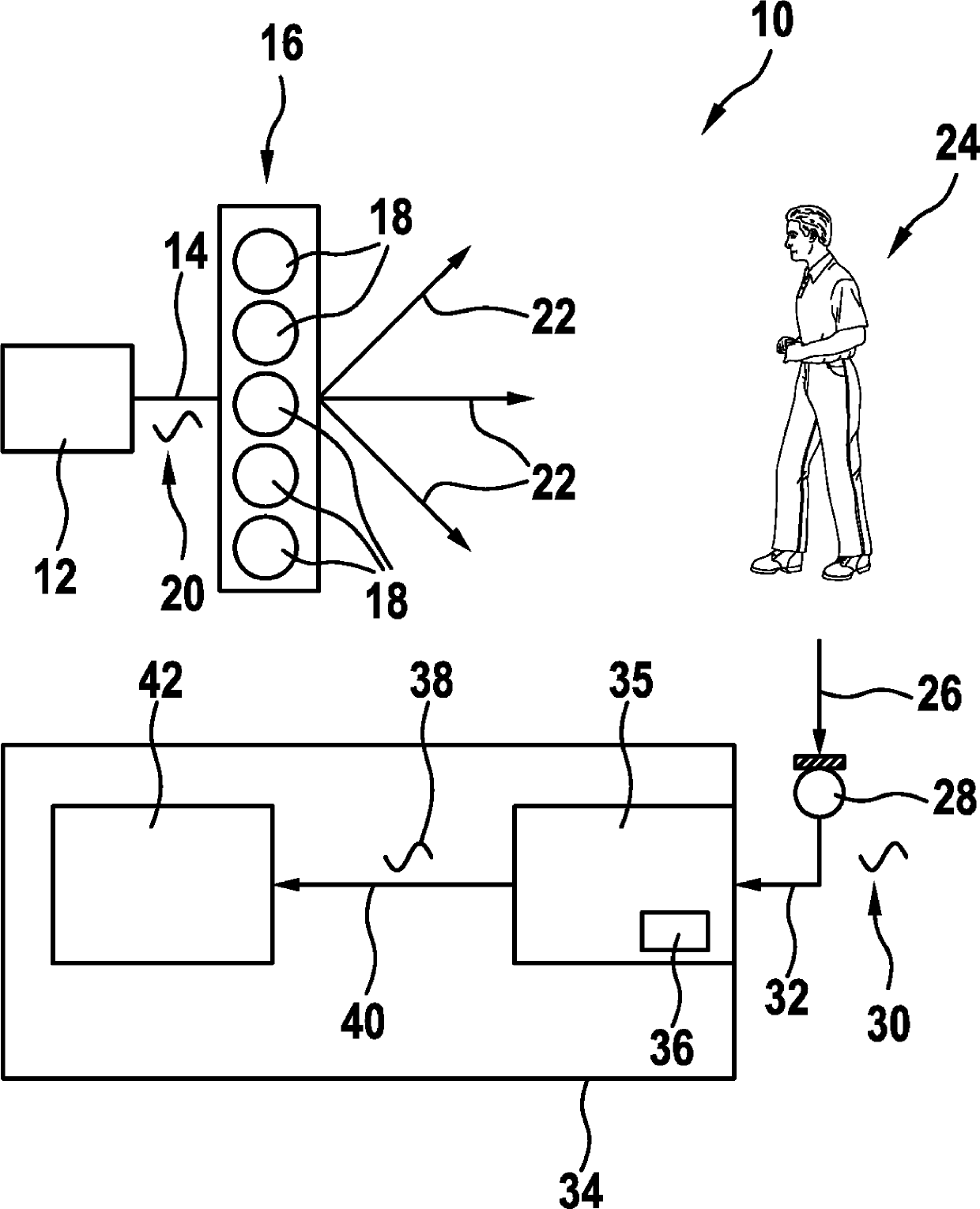
[0039] figure 1 The ultrasound measurement assembly 10 is shown schematically. It comprises a drive unit 12 connected via lines 14 to an array 16 of ultrasound transmitter elements 18 forming an ultrasound transducer. The drive unit 12 is generating a drive signal 20 which is transmitted via the line 14 to the array of ultrasound transmitter elements 16 . The ultrasound transmitter elements 18 are driven by drive signals 20 , wherein they generate ultrasound beams directed in multiple directions 22 simultaneously. The ultrasonic beam includes a plurality of ultrasonic waves of different wavelengths corresponding to the driving frequency of the driving signal 20 . As will be explained exemplarily later, the different waves spread into different directions 22 depending on the ratio between the wavelength and the dimension of each ultrasound transmitter element 18 . Thus, in different spatial directions 22 ultrasound waves of different frequency spectrums are emitted.

[0040...


PUM


Abstract

The present invention relates to an ultrasound measurement assembly (10) and a corresponding method for performing an ultrasound measurement. The ultrasound measurement assembly (10) and the method are aimed at driving an ultrasound transmitter element (18) for transmitting ultrasound waves, with a driving signal having a plurality of different driving frequencies simultaneously. A driving unit (12) generates at least one driving signal (20) for at least one corresponding ultrasound transmitter element (18). As an effect, each ultrasound transmitter element (18) will generate a multidirectional ultrasound wave. Additionally, a driving signal 20 is designed in such a manner that an overall ultrasound beam comprises individual frequency spectra in different spatial directions (22). If a part of overall ultrasound beam is reflected, a sensing signal (30) is generated by a sensing unit (28). The sensing signal (30) comprises an individual frequency spectrum. The sensing signal is received by a processing unit which determines the frequency spectrum, thereby determining which spatial direction (22) or spatial region the signal was sent.

Description

technical field [0001] The invention relates to an ultrasonic measurement assembly and a method for performing ultrasonic measurements. The invention also relates to an ultrasound transmitter for an ultrasound measurement assembly, and to a sensing assembly for an ultrasound measurement assembly. Background technique [0002] US 6,549,487 B2 describes a vehicle occupancy sensor using an acoustic system for determining the range, extent and direction of a target. The system consists of an ultrasound transmitter formed with an array of air chamber resonator elements driven in relative phase with respect to each other to produce a steered acoustic beam. In this case, a raster scan can be provided by deflecting the sound beam in different spatial directions and multiple measurements can be carried out in different spatial directions. The transducer array is tuned to a single resonant frequency in order to emit an acoustic beam. [0003] Raster scanning is required because the...

Claims


Application Information

Patent Timeline
Patent Type & Authority Applications(China)
IPC IPC(8): G01S15/42G01S7/52
CPCG01S15/42G01S15/08
Inventor W.J.拉姆布B.K.斯里德哈兰奈尔
Owner KONINKLJIJKE PHILIPS NV
Why Eureka
Try Eureka