Retractable castor mechanism of rack

A technology of cabinets and casters, applied in the direction of casters, wheels, transportation and packaging, etc., can solve the problems of inconvenient moving cabinets, poor load-bearing effect of casters, complicated installation, etc., achieve flexible and convenient handling, save installation costs, and improve installation efficiency Effect

Inactive Publication Date: 2014-05-21
深圳市阿尔法特网络环境有限公司
View PDF20 Cites 12 Cited by
  • Summary
  • Abstract
  • Description
  • Claims
  • Application Information

AI Technical Summary

Problems solved by technology

[0003] Therefore, the purpose of the embodiments of the present invention is to provide a retractable cabinet caster mechanism with good bottom load-bearing effect to solve the traditional cabinet due to the poor load-bearing effect of the casters and the need to make the bottom of the cabinet directly fall on the floor. The problem of inconveni

Method used


Image

  • Retractable castor mechanism of rack
  • Retractable castor mechanism of rack
  • Retractable castor mechanism of rack

Examples


Example Embodiment

[0020] Preferred embodiment one of the present invention

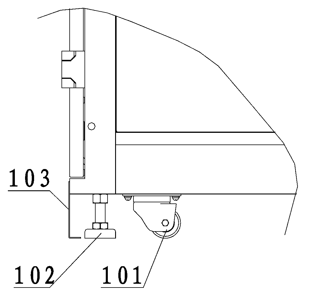
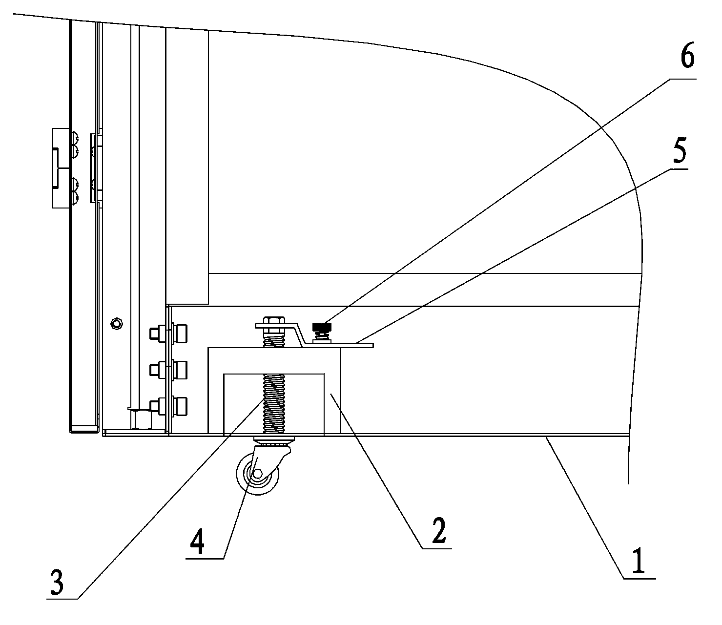
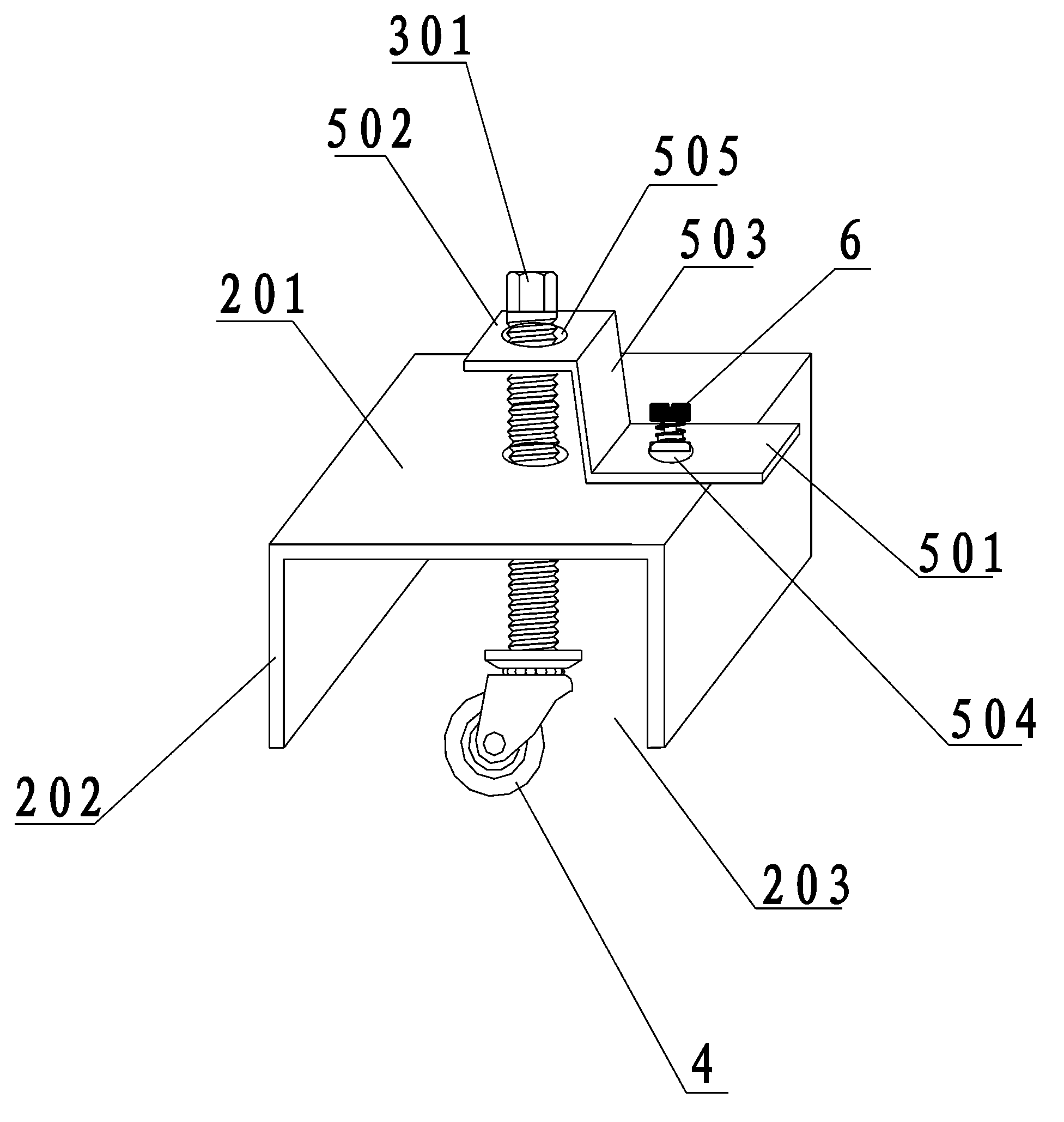
[0021] See figure 2 , image 3 as shown, figure 2 It is a schematic diagram of a cross-sectional structure installed at the bottom of the cabinet of the present invention; image 3 It is a schematic diagram of the cabinet caster installation structure in the preferred embodiment 1 of the present invention.

[0022] The retractable cabinet caster mechanism of the present invention is installed at the bottom of the cabinet, and includes a support member 2, a screw rod 3, an adjustment member 5 and a universal caster wheel 4. And the side plate 202 perpendicular to the top plate 201 is formed, and an accommodating groove 203 is formed in the support member 2 through the top plate 201 and the side plate 202 , and the bottom opening of the accommodating groove 203 is located on the bottom plate 1 of the cabinet.

[0023] The screw 3 is installed in the support 2, its top is set as a nut 301 above the support 2, and th...

Example Embodiment

[0025] Preferred embodiment two of the present invention

[0026] See figure 2 , Figure 4 as shown, figure 2 It is a schematic diagram of a cross-sectional structure installed at the bottom of the cabinet of the present invention; Figure 4 It is a schematic diagram of the cabinet caster installation structure of the second preferred embodiment of the present invention.

[0027] The retractable cabinet caster mechanism of the present invention is installed at the bottom of the cabinet, and includes a support member 2, a screw rod 3, an adjustment member 5 and a universal caster wheel 4. The support member 2 is a cylinder, and a housing is arranged in the cylinder The slot 203 , the bottom opening of the accommodating slot 203 is located on the bottom plate 1 of the cabinet.

[0028] The screw 3 is installed in the cylindrical support 2, its top is set as a nut 301 above the support 2, and the bottom is equipped with a swivel caster 4, and the swivel caster 4 can extend ...

Example Embodiment

[0030] Preferred embodiment three of the present invention

[0031] See figure 2 , Figure 5 as shown, figure 2 It is a schematic diagram of a cross-sectional structure installed at the bottom of the cabinet of the present invention; Figure 5 It is a schematic diagram of the cabinet caster installation structure of the third preferred embodiment of the present invention.

[0032] The retractable cabinet caster mechanism of the present invention is installed at the bottom of the cabinet, and includes a support member 2, a screw rod 3, an adjustment member 5 and a universal caster 4. The support member 2 is a rectangular body, and a housing is arranged in the rectangular body The slot 203 , the bottom opening of the accommodating slot 203 is located on the bottom plate 1 of the cabinet.

[0033] The screw 3 is installed in the rectangular support 2, the top of which is set as a nut 301 above the support 2, the bottom is equipped with a swivel caster 4, and the swivel cast...


PUM


Abstract

The invention discloses a retractable castor mechanism of a rack. The retractable castor mechanism is installed in the bottom of the rack, and comprises a supporting part, a screw and a universal castor, wherein an accommodating groove is arranged in the supporting part, an opening in the bottom of the accommodating groove is arranged in a base plate of the rack, the screw is arranged in the supporting part, the top of the screw is provided with a screw cap above the supporting part, the bottom of the screw is provided with the universal castor in the accommodating groove, and the universal castor can extend out of or can be retracted into the accommodating groove by virtue of the regulation of the screw. Compared with the traditional castor of the rack, the retractable castor mechanism of the rack, disclosed by the invention, is more flexible and convenient to transport, the installation cost of the rack is reduced, and the installation efficiency of the rack is improved. Therefore the retractable castor mechanism of the rack has the advantages of being simple in structure, easy to process, low in cost, practical, and capable of being applied to most of the racks.

Description

Technical field: [0001] The invention relates to a network communication cabinet, in particular to a network communication cabinet caster, and more specifically, a retractable cabinet caster mechanism. Background technique: [0002] The casters of traditional communication cabinets are fixed on the bottom of the cabinet by screws and nuts to facilitate the handling of the cabinet. When installing the cabinet, it is necessary to consider the load-bearing and bottom sealing effect after the cabinet is full of equipment, and usually the cabinet is full of equipment. Finally, the casters cannot bear the weight of the cabinet, so it is necessary to remove the casters and let the cabinet fall directly on the floor. Although this method has better load-bearing and sealing effects, when the cabinet needs to be moved again, it can only be lifted and moved manually. , not only inconvenient to operate but also labor-intensive to carry; and for cabinets with sealing requirements at the ...

Claims


Application Information

Patent Timeline
IPC IPC(8): B60B33/04
Inventor 骆恢兵
Owner 深圳市阿尔法特网络环境有限公司
Why Eureka
Try Eureka