
B-shaped subway vehicle body structure

A car body structure and vehicle technology, applied in railway car body, railway car body components, railway transportation, etc., can solve the problems of large longitudinal impact force, unfavorable car body strength, and small energy absorbed by coupler, and achieve good overall strength. and stiffness, improving local stress conditions, and reducing the effect of stress concentration

Active Publication Date: 2014-05-21
ZHUZHOU ELECTRIC LOCOMOTIVE CO
View PDF4 Cites 12 Cited by
  • Summary
  • Abstract
  • Description
  • Claims
  • Application Information

AI Technical Summary

Problems solved by technology

[0002] At present, the aluminum alloy car body of domestic B-type subway vehicles is limited by space constraints such as jumpers and couplers at the end of the vehicle. The end structure of the chassis is generally not equipped with traction guide beams or the traction guide beams do not extend to the end beams, and the force transmission effect is not good. As a result, the weld seam stress on the traction beam is relatively large, which can only meet the longitudinal load capacity of 800kN
In order to meet the headlights and styling requirements of the head car, the skeleton structure of the driver's cab is complicated, and many local reinforcement structures are set up. The force transmission path is not direct, which is not conducive to the improvement of the strength of the car body.
[0003] Since the vehicle body, which can only bear the longitudinal load capacity of 800kN, cannot withstand large longitudinal impact force, the coupler can only choose the type with a relatively small maximum crushing force value when the vehicle is collided. The energy absorbed by the coupler when the vehicle collides is relatively small. Small, difficult to meet EN 15227 crash performance requirements

Method used


Image

  • B-shaped subway vehicle body structure
  • B-shaped subway vehicle body structure
  • B-shaped subway vehicle body structure

Examples


Embodiment Construction

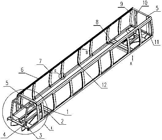
[0028] A type B subway car body structure, such as figure 1 Shown: side beams of the underframe 2, cab end beams 3, cab column 4, roof beam 5, roof side beam 6, door column 7, corner column 9, end wall column 10, underframe end beam 11, Side wall gussets 12, roof panels, side wall panels, end wall panels, floors and other components constitute an integrally loaded cylindrical structure. Wherein the top cover beam 5 is arranged in alignment with the door column 7 and the corner column 9 at the I end and the II end respectively, forming a simple force transmission path. The I-end structure 1 and the II-end structure 8 are mainly used to connect the car body and the bogie, and transmit the longitudinal force brought by the coupler to the side beam and the entire tubular structure.

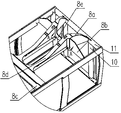
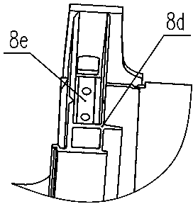
[0029] figure 2 It is a schematic diagram of the underframe structure at the non-cab end. II The end structure 8 is arranged at the end of the underframe of the car body, and the corbel 8c connect...


PUM


Abstract

The invention discloses a B-shaped subway vehicle body structure. In order to improve the longitudinal loading capacity of a vehicle body, the vehicle body structure comprises an integral loading barrel skeleton structure including chassis edge beams, cab end beams, cab columns, top cover cross beams, top cover edge beams, door columns, angle columns, end wall columns and chassis end beams; the barrel skeleton structure is fixed above a bogie; I-end traction guide beams are fixedly connected onto the cab end beams; II-end traction guide beams are fixedly connected onto the chassis end beams. The B-shaped subway vehicle body structure has high strength while keeping the light weight of the vehicle body, can bear 1,000 kN longitudinal load, provides a structure foundation for vehicle collision resistance design, is beneficial to improve the safety performance of the vehicle, and has better economic and social benefits.

Description

technical field [0001] The invention relates to an aluminum alloy car body structure capable of bearing a load of 1000kN for a B-type subway car, and belongs to the technical field of car body structures for rail transit vehicles. Background technique [0002] At present, the aluminum alloy car body of domestic B-type subway vehicles is limited by space constraints such as jumpers and couplers at the end of the vehicle. The end structure of the chassis is generally not equipped with traction guide beams or the traction guide beams do not extend to the end beams, and the force transmission effect is not good. As a result, the weld seam stress on the traction beam is relatively large, which can only meet the longitudinal load capacity of 800kN. In order to meet the headlights and styling requirements of the head car, the skeleton structure of the driver's cab is complicated, and many local reinforcement structures are set up. The force transmission path is not direct, which is...

Claims


Application Information

Patent Timeline
IPC IPC(8): B61D17/04
CPCY02T30/00
Inventor 刘永强苏柯岳译新刘厚林王锴钟磊阮思维董曾文
Owner ZHUZHOU ELECTRIC LOCOMOTIVE CO
Learn More