
Planetary rotary tray device

A rotating tray and planetary technology, which is applied in the mechanical field, can solve problems such as complex multi-chip device drivers, reduce the possibility of vibration, and improve deposition quality and uniformity

Active Publication Date: 2016-02-10
INST OF SEMICONDUCTORS - CHINESE ACAD OF SCI
View PDF8 Cites 0 Cited by
  • Summary
  • Abstract
  • Description
  • Claims
  • Application Information

AI Technical Summary

Problems solved by technology

If the chip carrier and the satellite rack are driven separately, the driver program in a multi-chip device will be more complicated

Method used


Image

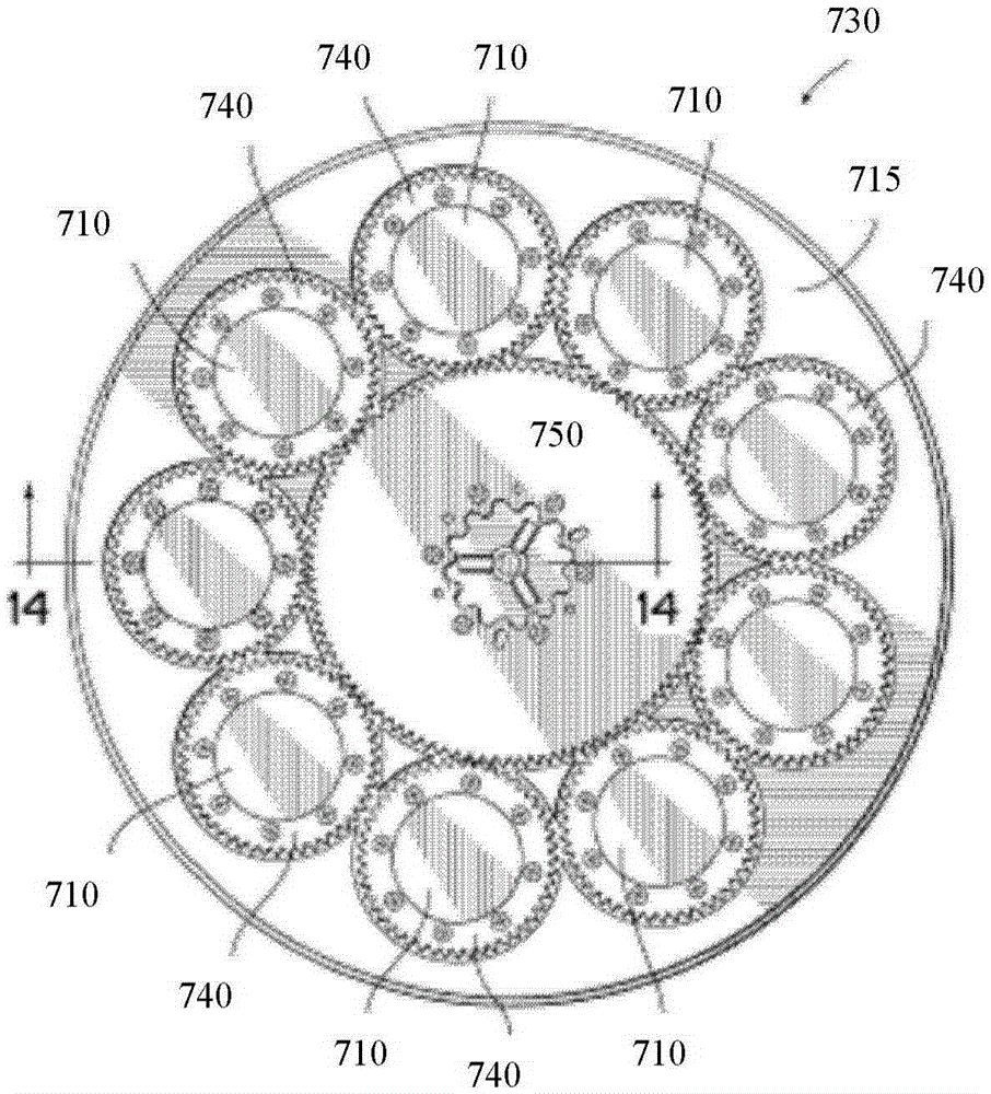
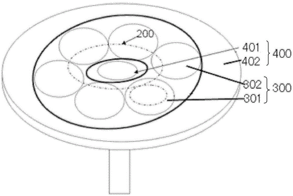
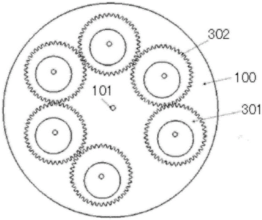
  • Planetary rotary tray device
  • Planetary rotary tray device
  • Planetary rotary tray device

Examples


Embodiment Construction

[0026] In order to make the object, technical solution and advantages of the present invention clearer, the present invention will be described in further detail below in conjunction with specific embodiments and with reference to the accompanying drawings. It should be noted that, in the drawings or descriptions of the specification, similar or identical parts all use the same figure numbers. Implementations not shown or described in the accompanying drawings are forms known to those of ordinary skill in the art. Additionally, while illustrations of parameters including particular values ​​may be provided herein, it should be understood that the parameters need not be exactly equal to the corresponding values, but rather may approximate the corresponding values ​​within acceptable error margins or design constraints. The directional terms mentioned in the embodiments, such as "upper", "lower", "front", "rear", "left", "right", etc., are only referring to the directions of the...


PUM


Abstract

The invention provides a planetary rotary tray device. The planetary rotary tray device comprises a dead plate, a sun gear and a satellite plate rail group, wherein a through hole is arranged at the center of the fixed plate; a ring-shaped concave track is arranged at the outer side of the fixed plate; a drive shaft extends into the ring-shaped concave track through the through hole; the sun gear is fixed at the frontage of the fixed plate and driven by the drive shaft to rotate around the through hole at the center of the fixed plate; the satellite plate rail group comprises a plurality of satellite plate rails which are arranged in the same radial direction; the bottoms of rotation shafts of the satellite plate rails are clamped into the ring-shaped concave track at the outer side of the fixed plate and capable of moving forwards and backwards along the ring-shaped concave track; the upper part of each satellite plate rail is provided with an upper gear; the upper gears of adjacent satellite plate rails are meshed with each other; the lower part of at least one satellite plate rail is provided with a lower gear which shares a rotation shaft with the upper gear thereof; and the lower gear and the sun gear are located at a same plane and meshed with each other. According to the planetary rotary tray device, the autorotation and revolution of each satellite plate rail can be realized.

Description

technical field [0001] The invention relates to the mechanical field, in particular to a planetary rotary tray device. Background technique [0002] Metal organic chemical vapor deposition system is a kind of equipment used for epitaxial growth of semiconductor thin films to form semiconductor devices. [0003] During the film growth process, it is necessary to heat under the tray, but due to various factors such as heat flux density and unbalanced distribution of reaction gas, the quality of the film at different positions above the tray is different. The tray in the prior art usually rotates around its center, so as to reduce the difference in film growth quality at different positions on the same radial direction above the tray. A planetary chemical vapor deposition structure allows each satellite frame to rotate independently while the tray rotates, further avoiding the difference in film quality at different distances from the epitaxial wafer to the center of the tray....

Claims


Application Information

Patent Timeline
Patent Type & Authority Patents(China)
IPC IPC(8): C30B25/12H01L21/687
Inventor 刘立莉杨华路红喜郭金霞李璟
Owner INST OF SEMICONDUCTORS - CHINESE ACAD OF SCI
Learn More