Fan main shaft calibration device

A technology for calibrating device and main shaft, applied in mechanical equipment, machine/engine, pump control and other directions, can solve the problems of large volume and weight of fan main shaft, high labor intensity of staff, inconvenient handling and fixing, etc., to improve detection efficiency and accuracy, reduce labor intensity of workers, and speed up production progress.

Inactive Publication Date: 2014-05-21
TIANJIN SANXIN SUNSHINE
View PDF0 Cites 0 Cited by
  • Summary
  • Abstract
  • Description
  • Claims
  • Application Information

AI Technical Summary

Problems solved by technology

[0002] Due to the large volume and weight of the fan shaft, it is not easy to carry and fix. It is very inconvenient to test the roundness, straightness, balance and other parameters of the fan shaft. Not only the labor intensity of the staff is high, but also the calibration The detection speed is slow and the precision is low, which seriously affects the production progress

Method used


Image

  • Fan main shaft calibration device
  • Fan main shaft calibration device

Examples


Embodiment Construction

[0017] The present invention will be further described in detail below through the specific examples, the following examples are only descriptive, not restrictive, and cannot limit the protection scope of the present invention with this.

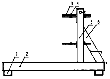
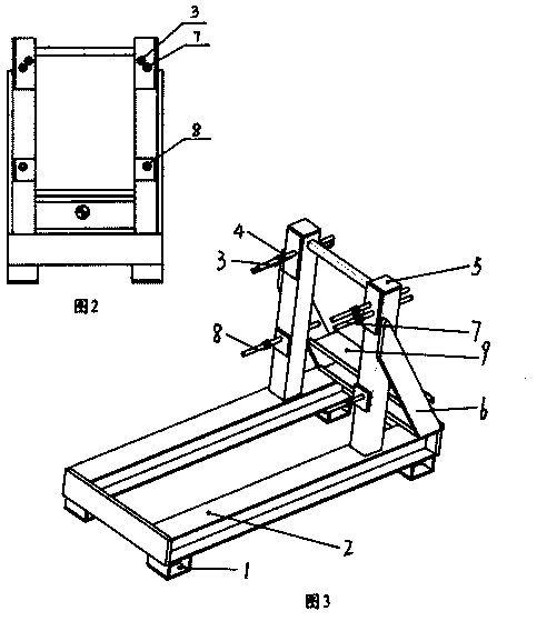
[0018] A fan shaft calibration device, comprising a base 2, a support column 5 and a positioning calibration rod, a plurality of legs 1 are installed on the lower surface of the base, two support columns are vertically installed side by side on the upper end surface of the base, each support column A rib 6 is installed between the outer side wall and the base, the two ribs are all positioned at the back of the support column, and a group of anti-slip pedals 9 are installed between the two ribs.

[0019] All wear a set of positioning and calibration rods on each support column, and the coaxial sleeve calibration nut 4 is positioned on the positioning calibration rod on the front of the support column, and there are two nuts. The top of each s...


PUM


Abstract

The invention relates to a fan main shaft calibration device. The fan main shaft calibration device comprises a base, supporting columns and positioning calibration rods, wherein two supporting columns are vertically installed on the upper end surface of the base side by side, and a group of positioning calibration rods is installed on each supporting column in a penetrating manner. The fan main shaft calibration device is simple in structure, ingenious in design, easy to manufacture, convenient to use and strong in practicability. By utilizing the fan main shaft calibration device, a main shaft can be supported and fixed, so that the calibration efficiency and the calibration precision can be improved, the labor intensity of workers can be alleviated, and the production progress can be accelerated.

Description

technical field [0001] The invention relates to a support inspection device in the field of fan manufacturing, in particular to a fan main shaft calibration device. Background technique [0002] Due to the large volume and weight of the fan shaft, it is not easy to carry and fix. It is very inconvenient to test the roundness, straightness, balance and other parameters of the fan shaft. Not only the labor intensity of the staff is high, but also the calibration The detection speed is slow and the accuracy is low, which seriously affects the production progress. Contents of the invention [0003] The purpose of the present invention is to overcome the deficiencies of the prior art and provide a fan shaft calibration device with reasonable design, simple structure, convenient use, and time-saving and labor-saving. [0004] The present invention solves its technical problem and realizes through the following technical solutions: [0005] A fan shaft calibration device, chara...

Claims


Application Information

Patent Timeline
Patent Type & Authority Applications(China)
IPC IPC(8): F04D27/00
Inventor 曹润星李卫华李凤元李国兴王永兴
Owner TIANJIN SANXIN SUNSHINE
Why Eureka
Try Eureka