Lens unit, light source module and light-emitting device

A technology of lens unit and light source module, applied in the direction of light source, lighting device, point light source, etc., can solve the problems of increasing the usage of manufacturing materials, increasing the manufacturing cost, increasing the overall height of the light-emitting device, etc.

Inactive Publication Date: 2014-05-21
DELTA ELECTRONICS INC
View PDF4 Cites 3 Cited by
  • Summary
  • Abstract
  • Description
  • Claims
  • Application Information

AI Technical Summary

Problems solved by technology

Although the lens unit 62 can effectively reduce the assembly process and assembly time for assembling the lens unit 62 and the light emitting diode 61, yet, the volume of the base 620 for riding the lens element 622 is much larger than the lens element 622, thus, it will increase The amount of productio...

Method used


Image

  • Lens unit, light source module and light-emitting device
  • Lens unit, light source module and light-emitting device
  • Lens unit, light source module and light-emitting device

Examples


Embodiment Construction

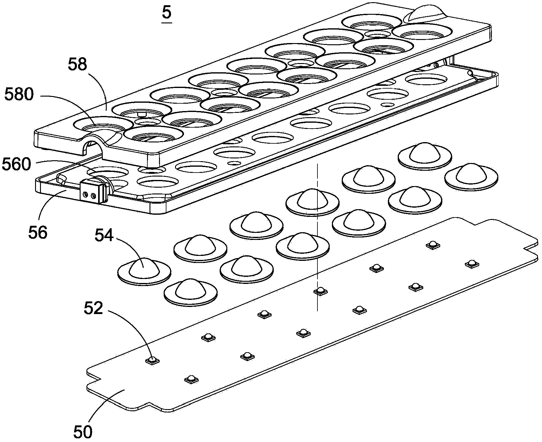
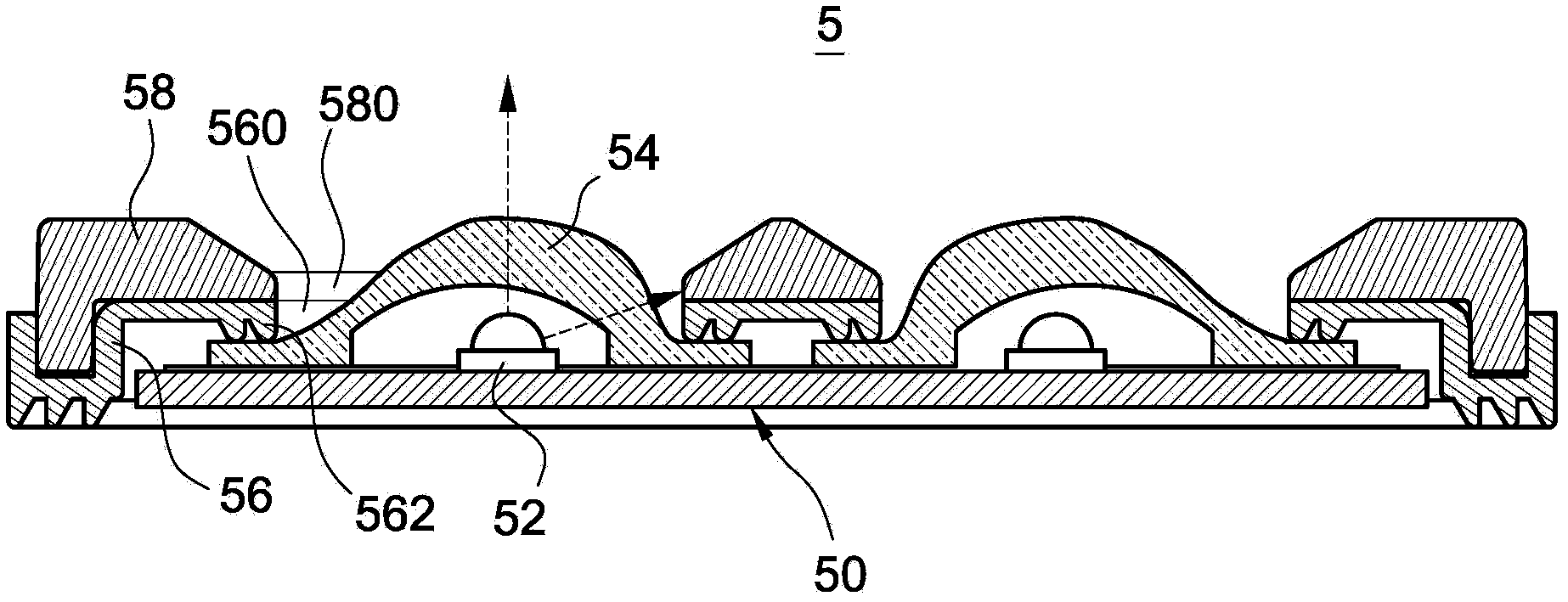
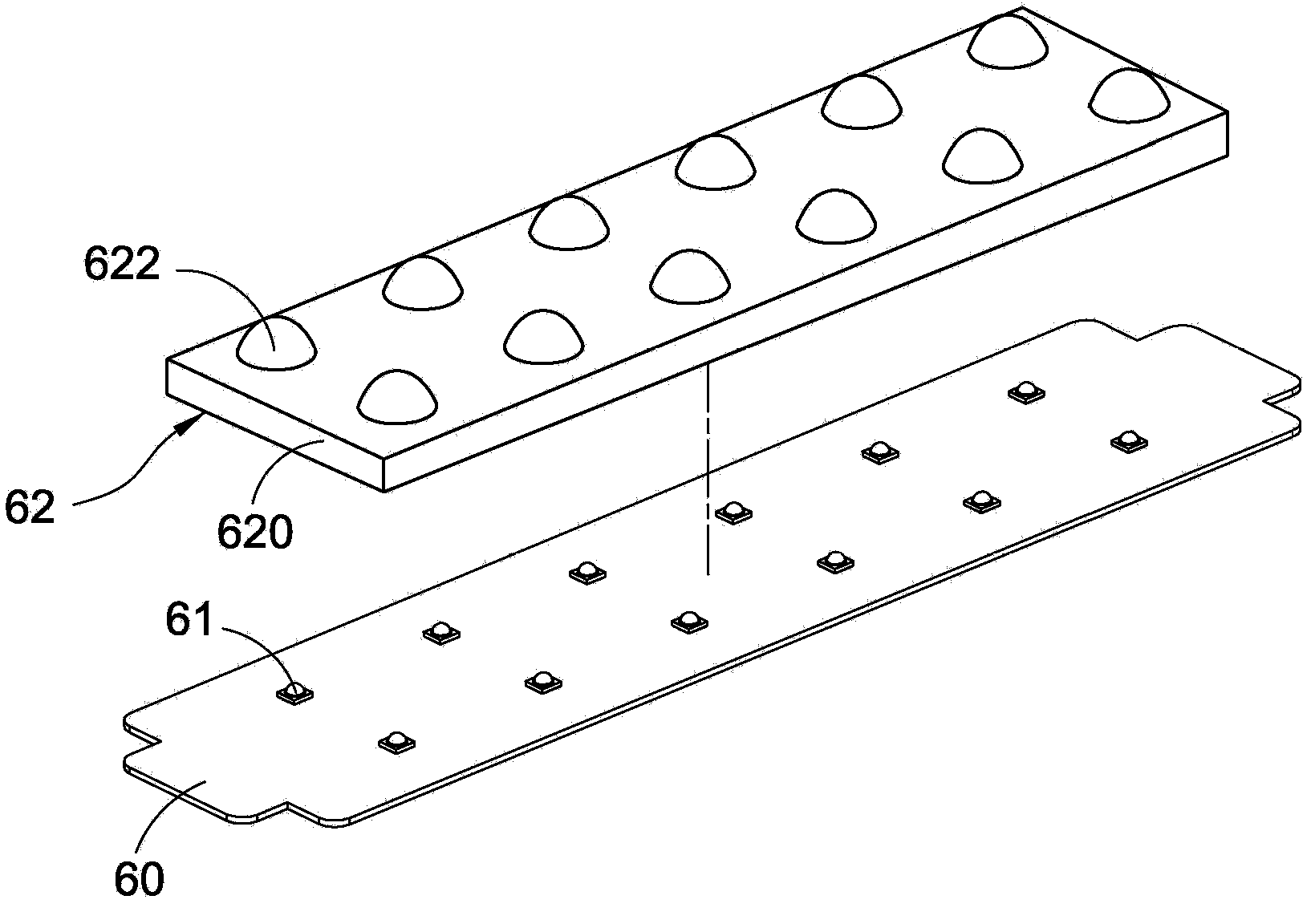
[0054] Cooperate with reference Figure 4 and Figure 5 , is a three-dimensional exploded view and a three-dimensional assembled view of the light source module according to the first embodiment of the present invention. The light source module 1 includes a light emitting unit 10 and a lens unit 12 . The lens unit 12 is disposed on the light emitting unit 10 for adjusting the light intensity distribution of the light emitted by the light emitting unit 10 .

[0055] The light emitting unit 10 is used to provide the light source required by the light source module 1 . The light emitting unit 10 includes a circuit board 100 and a plurality of light emitting elements 102 . The circuit board 100 may be a printed circuit board (PCB), a metal core PCB or a ceramic circuit board. The circuit board 100 includes a groove 104, the groove 104 has a predetermined depth D (such as Figure 6 shown); in this embodiment, the cross section of the trench 104 is substantially rectangular and r...


PUM


Abstract

The invention discloses a lens unit, a light source module and a light-emitting device. The lens unit comprises a connecting piece and a plurality of lens elements, wherein the connecting piece has a first thickness; each lens unit comprises a light shaping part and a base part; each base part has a second thickness, and surrounds the light shaping part; the second thickness is smaller than the first thickness; each base part is connected to the connecting piece; the upper surface of each base part and the upper surface of the connecting piece are positioned on the same horizontal plane. By adopting the lens unit disclosed by the invention, the assembly procedure and assembly time for assembling the lens unit on a light-emitting unit can be shortened.

Description

technical field [0001] The invention relates to a lens unit, a light source module and a light emitting device, in particular to a contiguous lens unit, a light source module and a light emitting device with the contiguous lens unit. Background technique [0002] Cooperate with reference figure 1 and figure 2 , are respectively an exploded perspective view and a cross-sectional view of a conventional light-emitting device. The light emitting device 5 includes a circuit board 50 , a plurality of LEDs 52 , a plurality of lens elements 54 , a waterproof element 56 and a cover 58 . The circuit board 50 is a flat plate, and the light-emitting diodes 52 are arranged in groups of two and equally spaced on the circuit board 50 and are electrically connected with the circuit board 50; the lens elements 54 are correspondingly arranged on the light-emitting diodes 52 for redistribution. light from the LED 52, and output a light with a specific light intensity. The waterproof membe...

Claims


Application Information

Patent Timeline
IPC IPC(8): F21V5/04F21Y101/02
Inventor 吴享珍黄智远陈立铭
Owner DELTA ELECTRONICS INC
Why Eureka
Try Eureka