Method for simulating cementation failure caused by temperature change

A technology of temperature change and cementing glue, applied in the direction of instruments, measuring devices, and mechanical devices, etc., can solve the problems of high experimental research cost, incomplete channeling range, and inability to reflect more comprehensively.

Active Publication Date: 2014-05-21
CHINA NAT OFFSHORE OIL CORP +4
View PDF5 Cites 10 Cited by
  • Summary
  • Abstract
  • Description
  • Claims
  • Application Information

AI Technical Summary

Problems solved by technology

At present, the equipment generally cannot guarantee that the cement slurry can be cemented in the same set of equipment and the temperature-bonding failure experiment is carried out, which is inconsistent with the actual working conditions;
[0008] 3) Gas channeling cannot be quantitatively evaluated
In terms of the length of the simulated cement sheath, it is generally less than 50cm, and the length is too small, which cannot fully reflect the problems existing in the actual working conditions in the experiment;
[0010] 5) The scope of inspection is not comprehensive
It is impossible to detect the working condition that a micro-annulus is formed in the middle of the height direction of the cement sheath and the two ends are well cemented
[0011] 6) High experimental cost
The inner casing cemented with the cement sheath, the outer artificial formation or the casing are scrapped after one experiment, resulting in high cost of experimental research
[0012] 7) The parameters of the experimental conditions are low, and it is impossible to simulate the working conditions of high temperature and high pressure wells at the same time

Method used


Image

  • Method for simulating cementation failure caused by temperature change

Examples


Embodiment approach 1

[0051] Embodiment 1: Cement slurry formula 1 is under a constant confining pressure of 30MPa, the inner pressure of the casing is 25MPa, the initial temperature is 60°C, the temperature rises rapidly to 120°C within 30-40 minutes, and the temperature is kept constant for 3-4hrs, and then the cement sheath and the outer casing are inspected Whether there is a micro-annulus between the interfaces, and check the gas channeling flow rate at the same time; if micro-cracks are found, exclude formula 1, continue to test formula 2, formula 3..., find out the cement slurry formula that has not been damaged and determine it as initially suitable. Then cool down naturally or slowly (about 4 hours) to 60°C, and use the initially suitable formula to repeat steps to raise the temperature to 120°C, and the formula that can withstand the most repeated heating and cooling times when channeling occurs is the best.

Embodiment approach 2

[0052] Embodiment 2: Cement slurry formula 1 is at a constant confining pressure of 30MPa, the pressure inside the casing is 25MPa, the initial temperature is 60°C, the temperature rises rapidly to 160°C within 40-50 minutes, and the temperature is kept constant for 3-4hrs, and then the cement sheath and the outer casing are inspected Whether there is a micro-annulus between the interfaces, and check the gas channeling flow rate at the same time; if micro-cracks are found, exclude formula 1, continue to test formula 2, formula 3..., find out the cement slurry formula that has not been damaged and determine it as initially suitable. Then cool down naturally or slowly (about 4 hours) to 60°C, and use the formula that is initially considered suitable to repeat the steps to raise the temperature to 160°C, and the formula that can withstand the most repeated heating and cooling times when channeling occurs is the best.

Embodiment approach 3

[0053] Implementation Mode 3: Cement slurry formula 1 is under constant confining pressure of 35MPa, casing internal pressure of 30MPa, initial temperature of 140°C, temperature rapidly drops to 60°C within 40-50 minutes, constant temperature for 3-4hr, and then inspects cement sheath and outer casing Whether there is a micro-annulus between the interfaces, and check the gas channeling flow rate at the same time; if micro-cracks are found, exclude formula 1, continue to test formula 2, formula 3..., find out the cement slurry formula that has not been damaged and determine it as initially suitable. , use the initially suitable formula to repeat the above steps to raise the temperature to 140°C and then cool down naturally or slowly (about 4 hours) to 60°C, and the formula that can withstand the most repeated heating and cooling times when channeling occurs is the best.

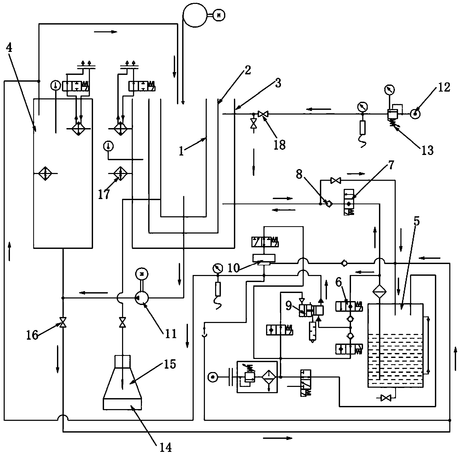
[0054] see figure 1 , the method for checking the flow of gas channeling in the above-mentioned embodiment ...


PUM


Abstract

The invention discloses a method for simulating cementation failure caused by temperature change. The method comprises the steps of mounting a bushing component and injecting cement slurry into the bushing component; placing the bushing component into a high-pressure kettle of a test device, and closing the tops of the bushing component and the high-pressure kettle; filling the bushing component with high-pressure oil, and heating the bushing component; pressurizing a ring space between the high-pressure kettle and the bushing component, heating the high-pressure kettle, adjusting the temperature and the pressure in the high-pressure kettle to be consistent with the temperature and the pressure under an actual downhole working condition, and maintaining the cement slurry until a cement ring is molded; keeping the pressure between the high-pressure kettle and the bushing component and in the bushing component to be constant, detecting whether gas channeling exists between the cement ring and a bushing in a temperature change process by repeated heating and cooling, and measuring a gas channel amount, wherein a formula of the cement ring which can be repeatedly heated and cooled for most times is taken as the best formula. According to the method, simulation of an engineering working condition is realized indoors, data and parameters which have guiding significance for the engineering practice are obtained, and the optimal formula of the cement ring can be found.

Description

technical field [0001] The invention relates to a test method for indoor simulating cementation in well cementing, in particular to a test method for indoor simulating the influence of temperature changes on cementation in cementing. Background technique [0002] In well cementing, the sealing performance of the cement sheath to the formation is of great significance to the production safety, life of the oil and gas well and the benefits of oil field development. The cement sheath with high sealing and channeling ability is safe and environmentally friendly to develop the oil layer and realize the maximum exploration and development benefits. an important basis for transformation. [0003] Actual production experience shows that after the cement slurry is replaced in place, the CBL / VDL test shows that the well with good cementing quality will undergo subsequent drilling, drilling fluid density increase, formation integrity test, perforation, fracturing, temperature change, p...

Claims


Application Information

Patent Timeline
Patent Type & Authority Applications(China)
IPC IPC(8): G01N19/04
Inventor 谢玉洪张勇罗宇维黄凯文李炎军张超徐一龙朱江林邓金根王玉田
Owner CHINA NAT OFFSHORE OIL CORP
Why Eureka
Try Eureka