An electric energy metering device and method
An electric energy metering device and electric energy metering technology are applied in measuring devices, measuring electric variables, and measuring time integration, etc., which can solve problems such as multi-loop centralized collection and communication loops, and achieve the effects of easy installation and maintenance, small size, and convenient installation
- Summary
- Abstract
- Description
- Claims
- Application Information
AI Technical Summary
Problems solved by technology
Method used
Image
Examples
Embodiment 1
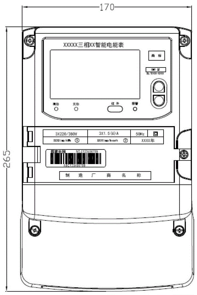
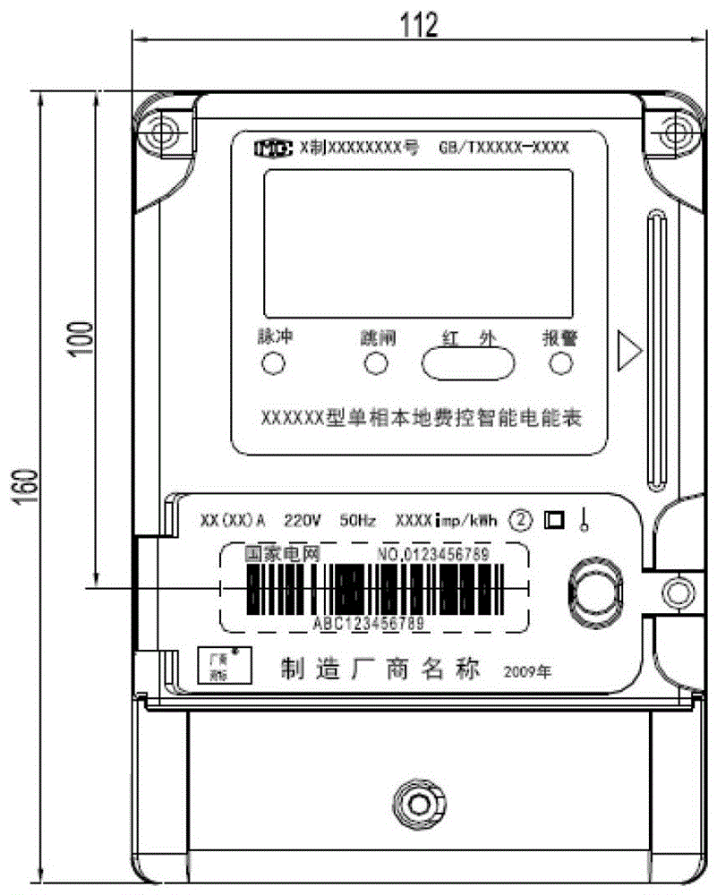
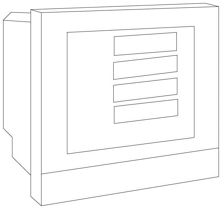
[0072] This embodiment provides an electric energy metering device, such as Figure 5 and 6 As shown, the electric energy metering device includes an internal component 1 and an external component 2 . The internal components 1 include: at least 2 external current acquisition modules 11, a common voltage acquisition module 12, an electric energy metering circuit module 13, a main control chip module 14, a Zigbee communication module 15, a power supply module 16, and a real-time clock Module 17, external memory module 18, indicating circuit module 19, see Figure 5 . The external assembly 2 includes: a housing 21, a rail groove assembly 22, a terminal assembly 23, and an external antenna 24, see Figure 6 .
[0073] see Figure 5 , the external current collection module 11 is used to collect the current of the circuit to be tested. Further, the current acquisition module 11 includes a split current sensor; the split current sensor includes a Rogowski coil, or / and a split c...
Embodiment 2
[0101] This embodiment provides an electric energy metering device, such as Figure 10 As shown, the difference from Embodiment 1 is that the electric energy metering circuit module includes 6 current sampling channels, 1 shared voltage sampling channel, metering chip and 2 meter calibration pulse output channels; the metering chip includes 2 three-phase metering chip; each three-phase metering chip is connected to three current sampling channels, one common voltage sampling channel and one calibration pulse output channel; A voltage comes from a shared voltage sampling module and a shared voltage sampling channel (voltage sampling channel 1), the shared voltage sampling channel is a single-phase voltage sampling channel; three current sampling channels of two three-phase metering chips The current values collected by the respective current sampling modules are respectively transmitted, and the electric energy metering of single-phase 6 circuits is realized.
Embodiment 3
[0103] This embodiment provides an electric energy metering device, such as Figure 11As shown, the difference from Embodiment 1 is that the electric energy metering circuit module includes 6 current sampling channels, 1 shared voltage sampling channel, metering chip and 2 meter calibration pulse output channels; the metering chip includes 2 Each three-phase metering chip is connected to three current sampling channels, one common voltage sampling channel and one meter calibration pulse output channel; that is, the three-phase voltages of the two three-phase metering chips come from the Shared voltage sampling channel (channel 1 for voltage, channel 2 for voltage, channel 3 for voltage), the shared voltage sampling channel is a three-phase voltage sampling channel; the voltage value collected by each shared voltage acquisition module is passed through a shared The voltage sampling channel of the two metering chips is transmitted to the metering chip, and the three current samp...
PUM
 Abstract
Description
Claims
Application Information
 - R&D Engineer
- R&D Manager
- IP Professional
- Industry Leading Data Capabilities
- Powerful AI technology
- Patent DNA Extraction
Browse by: Latest US Patents, China's latest patents, Technical Efficacy Thesaurus, Application Domain, Technology Topic, Popular Technical Reports.
© 2024 PatSnap. All rights reserved.Legal|Privacy policy|Modern Slavery Act Transparency Statement|Sitemap|About US| Contact US: help@patsnap.com


