Robot positioning system and reflection device identification method thereof

A robot positioning and reflection device technology, which is applied to measuring devices, radio wave measuring systems, instruments, etc., can solve the problems of complicated program design and aggravated processing chip burden, and achieve the effect of reducing computing burden and positioning error

A robot positioning and reflection device technology, which is applied to measuring devices, radio wave measuring systems, instruments, etc., can solve the problems of complicated program design and aggravated processing chip burden, and achieve the effect of reducing computing burden and positioning error

CN103809184AActive Publication Date: 2014-05-21SUZHOU CLEVA PRECISION MACHINERY & TECH

Image

  • Robot positioning system and reflection device identification method thereof
  • Robot positioning system and reflection device identification method thereof
  • Robot positioning system and reflection device identification method thereof

Examples


Embodiment Construction

[0020] The present invention will be further described below in conjunction with the accompanying drawings.

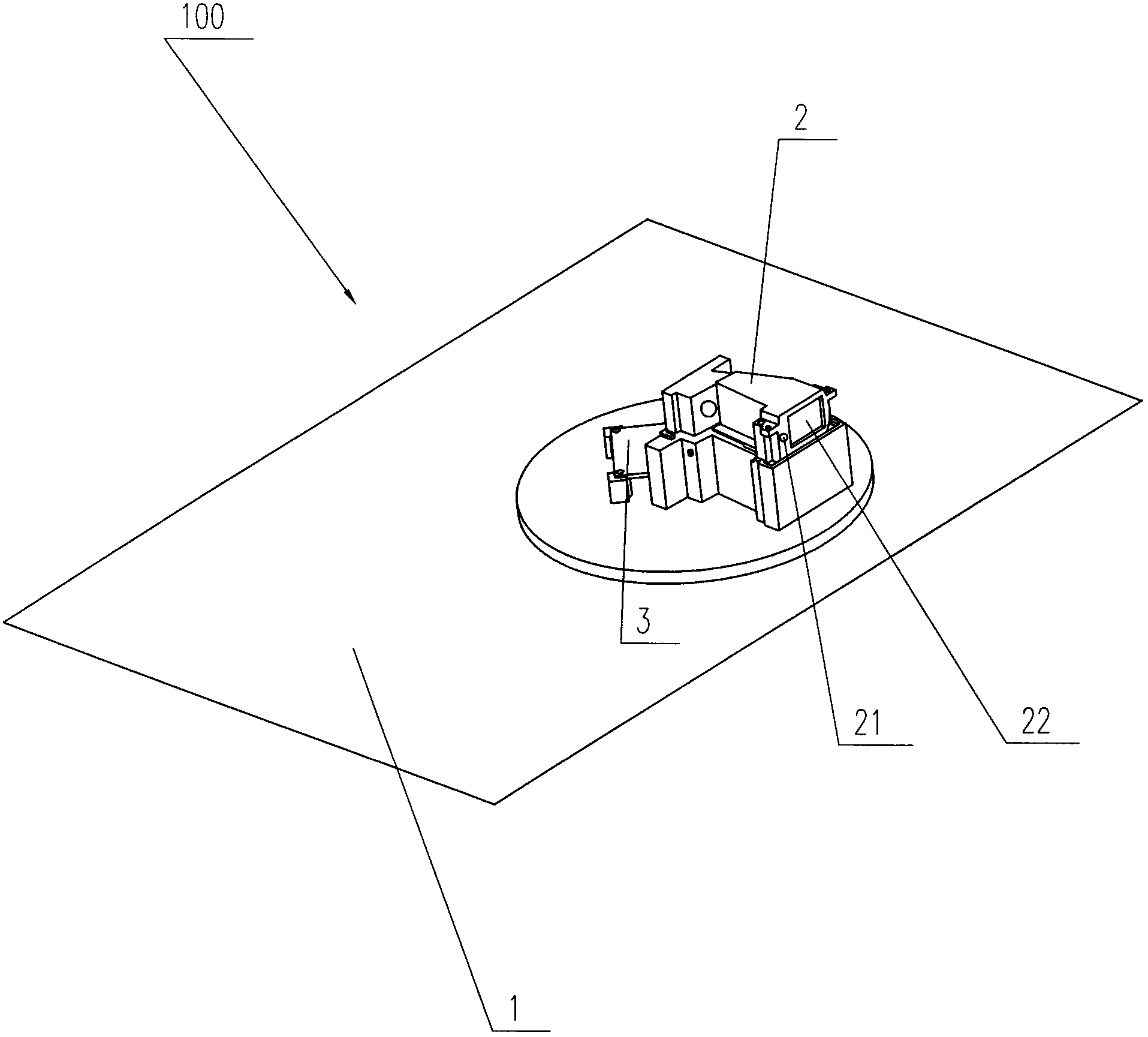
[0021] The robot positioning system of this embodiment includes a movable automatic mowing robot, which can automatically mow the lawn. Such as figure 1 As shown, the mowing robot 100 includes a signal system for sending and receiving signals, a processing system for calculating and judging, and a walking system for moving the robot. The robot 100 includes a car body 1, and the car body 1 has wheels or crawlers (not shown in the figure) ), enabling the robot to move on the ground. The car body 1 is provided with a signal system 2, which includes a laser emitting device 21 and a laser receiving device 22. The laser emitting device 21 can rotate at a certain speed around an axis perpendicular to the car body at a horizontal direction of 360°, so that the laser light can be continuously obtained. Sweep around the car body, and the laser that the launcher 21 sends can al...


PUM


Abstract

The invention discloses a robot positioning system and a reflection device identification method thereof. The robot positioning system comprises a mobile robot and at least two reflection devices. The robot is provided with a laser emitting device and a laser receiving device. The reflection devices can reflect received laser, each reflection device is provided with reflection members, and the reflection devices have different numbers of reflection members. When laser emitted by the laser emitting device scans any reflection device, the laser receiving device outputs a signal every time the laser receiving device receives reflected laser of the reflection device, and the robot can directly determine which reflection device is currently scanned according to the number of received signals. According to the technical scheme provided by the invention, the robot can rapidly identify the reflection devices in the movement process so that the coordination position of the robot can be determined by utilizing the reflection devices, the operation load of a processing system is mitigated, and the positioning error of the robot is reduced.

Description

technical field [0001] The invention relates to a robot positioning system and its positioning method, in particular to a laser reflection positioning system and its positioning method. Background technique [0002] In the prior art, there are many ways to determine the position of the mobile robot when it moves in space, such as using GPS positioning, ultrasonic or laser positioning. The laser positioning system usually installs a laser emitting device and a laser receiving device on the mobile robot, and sets multiple laser reflecting devices in the moving area of ​​the robot, and calculates the coordinate position of the robot in the moving area through the laser reflecting device of the known coordinate position. Using the positioning system that sets the reflection device to determine the position of the mobile robot, the coordinates of each reflection device in the coordinate system need to be known, and the coordinates of each reflection device are stored in the robot...

Claims


Application Information

Patent Timeline
21 May 2014
Publication
CN103809184A
IPC
G01S17/02; G01S17/875
CPC
G01S17/42; G01S17/875
Inventors
孔钊; 姜飞