Matrix converter output voltage controlling method

A technology of output voltage control and matrix converter, which is applied in the direction of conversion equipment that can be converted to DC without intermediate conversion, and can solve the problem of limited capacity of output voltage distortion

Active Publication Date: 2014-05-21
INVT POWER ELECTRONICS SUZHOU CO LTD
View PDF6 Cites 0 Cited by
  • Summary
  • Abstract
  • Description
  • Claims
  • Application Information

AI Technical Summary

Problems solved by technology

[0005] In view of this, the present invention provides a matrix converter output voltage control method to solve the problem of limited ability to improve output voltage distortion in the prior art

Method used


Image

  • Matrix converter output voltage controlling method
  • Matrix converter output voltage controlling method
  • Matrix converter output voltage controlling method

Examples


Embodiment Construction

[0043] The following will clearly and completely describe the technical solutions in the embodiments of the present invention with reference to the accompanying drawings in the embodiments of the present invention. Obviously, the described embodiments are only some, not all, embodiments of the present invention. Based on the embodiments of the present invention, all other embodiments obtained by persons of ordinary skill in the art without making creative efforts belong to the protection scope of the present invention.

[0044] The invention provides a method for controlling the output voltage of a matrix converter to solve the problem of very limited ability to improve output voltage distortion in the prior art.

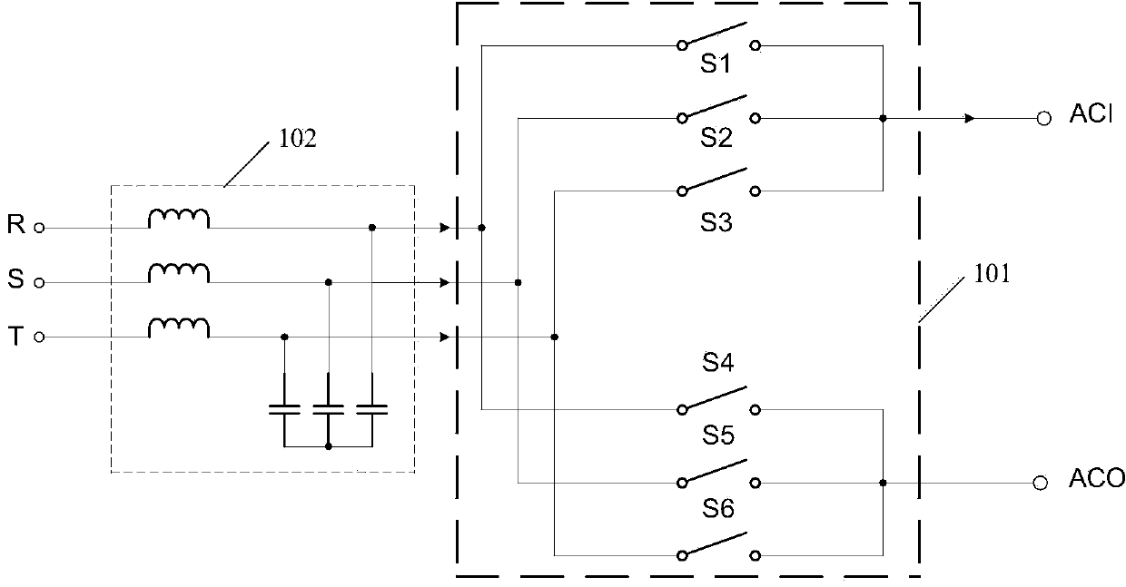
[0045] The matrix converter output voltage control method is applied to a matrix converter, and the matrix converter includes: a controller and a power switch matrix; specifically, as Figure 4 As shown, the matrix converter output voltage control method includes:

...


PUM


Abstract

The invention discloses a matrix converter output voltage controlling method. Effective vectors and control factors capable of increasing effective vector action time are selected during operation of a matrix converter under low modulation coefficient through judgment of a controller; action time of the effective vectors and zero vectors is calculated; on the basis of the above action time, reference output voltage sectors and input voltage sector information, a new vector switching order is arranged according to a principle that the action time of each zero vector is not smaller than a switch conversion current period; a power switch matrix is controlled to be switched on or off according to the new vector switching order; pulses of driving waveforms can be broadened by the new vector switching order, and narrow pulses of the driving waveforms can be effectively eliminated; the time of the effective vectors is increased, the probability of conversion current errors caused by the fact that the action time of the effective vectors are smaller than the switch conversion current period is greatly reduced, and thereby, output voltage distortion is reduced.

Description

technical field [0001] The invention relates to the technical field of power conversion, in particular to a method for controlling the output voltage of a matrix converter. Background technique [0002] Three-phase-single-phase matrix converter such as figure 1 As shown, it includes: 6 bidirectional power switches Sx (x is a positive integer greater than or equal to 1 and less than or equal to 6) according to a 3×2 matrix topology to form a power switch matrix 101 and an input LC filter 102; the input terminal of the matrix converter R, S, and T are connected to the three-phase power grid, and the output terminals ACI and ACO are connected to the load; the specific implementation form of the bidirectional power switch Sx is figure 2 As shown, Sx+ is an IGBT (Insulated Gate Bipolar Transistor, insulated gate bipolar transistor) near the input side, and Sx− is an IGBT near the output side. [0003] The dual-voltage modulation strategy adopted by the matrix converter is: wit...

Claims


Application Information

Patent Timeline
IPC IPC(8): H02M5/22
Inventor 陈善开王凯张波
Owner INVT POWER ELECTRONICS SUZHOU CO LTD
Why Eureka
Try Eureka