Latch device

一种闩锁装置、闩锁的技术,应用在闩锁装置领域,能够解决闩锁不能扣合、不能座位或可移动的座位固定到地板表面等问题

Inactive Publication Date: 2014-05-21
MITSUI KINZOKU ACT
View PDF7 Cites 4 Cited by
  • Summary
  • Abstract
  • Description
  • Claims
  • Application Information

AI Technical Summary

Problems solved by technology

[0004] By the way, when the distance between the hinge shaft and the catch is shorter or longer than the reference distance due to the installation error of the hinge shaft or the catch, etc., the latch cannot be engaged with the catch, and therefore, cannot Secure removable or removable seats to floor surfaces

Method used


Image

  • Latch device
  • Latch device
  • Latch device

Examples


Embodiment 1

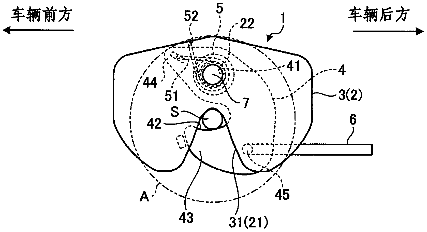
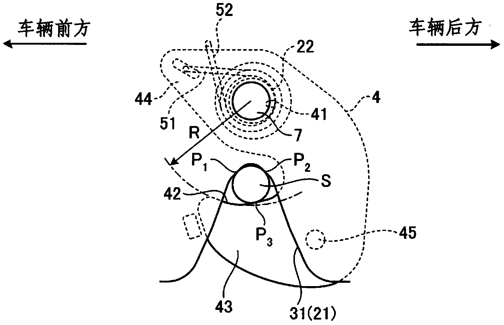
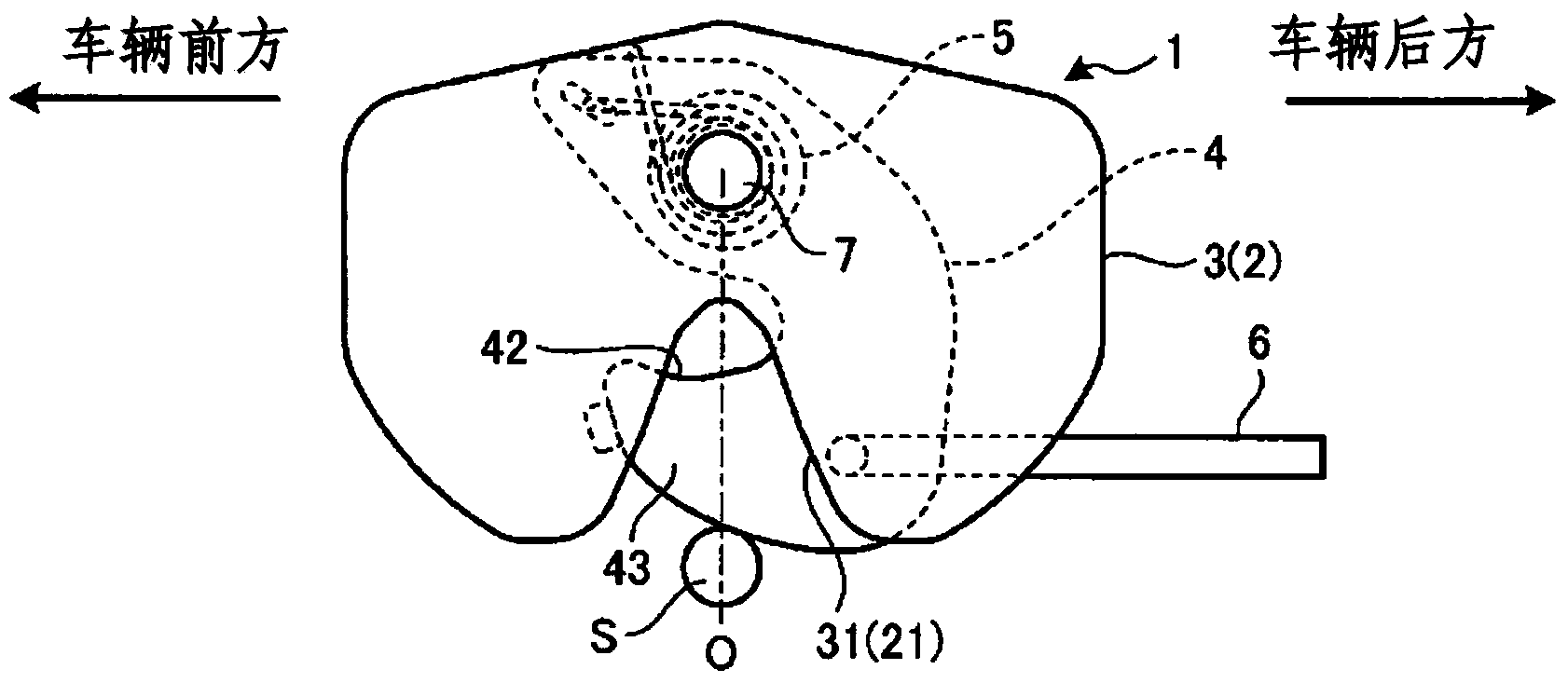
[0055] figure 1 is a conceptual diagram showing the configuration of the latch device according to Embodiment 1 of the present invention. figure 2 is shown figure 1 An enlarged view of the relationship between the latch and access slot shown.

[0056] The latching device 1 illustrated here as an example is used to secure a detachable seat or a movable seat and comprises a housing consisting of a base plate 2 and a cover plate 3 which is connected to the base plate 2 in such a way that it is superimposed on the base plate 2 And the cover plate 3 is connected to the seat. Furthermore, a latch accommodating portion is defined between the bottom plate 2 and the cover plate 3, and a latch 4 is accommodated inside the latch accommodating portion. Like conventional latches, the latch 4 is designed to snap-fit ​​with a striker S provided on the floor surface.

[0057] In addition, entry grooves 21, 31 are respectively formed at substantially longitudinal center positions in the f...

Embodiment 2

[0081] Figure 6 is a conceptual diagram showing the configuration of the latch device according to Embodiment 2 of the present invention. also, Figure 7 illustrated in detail Figure 6 cylindrical latch shaft shown, and Figure 8 illustrated in detail Figure 6 The elongated hole shown.

[0082] The latch device of Embodiment 2 of the present invention further adds a second fastening element 8 on the basis of the latch device 1 of Embodiment 1 above, and the same reference numerals will be used to denote the same reference numerals as those of the latch device 1 of Embodiment 1 above. The configurations of the lock devices are the same, and their descriptions will be omitted here.

[0083] Such as Figure 6 As shown, the second fastening element 8 is used to fix the bottom plate 2 and the cover plate 3 so that they move with the fastening element 7 relative to the buckle S, and the second fastening element 8 is inserted through the arc-shaped elongated Holes 23 , 33 a...

Embodiment 3

[0094] Figure 11 is a conceptual diagram showing the structure of a latch device according to Embodiment 3 of the present invention. Figure 12 is shown figure 1 An enlarged view of the relationship between the latch and access slot shown.

[0095] Like the latch device described in Embodiment 1 above, the latch device 101 described here as an example is used to fix a detachable seat or a movable seat, and includes a base plate 102 and is connected in a manner superimposed on the base plate 102 The cover plate 103 of the bottom plate 102 . Furthermore, a hook accommodating portion is defined between the base plate 102 and the cover plate 103, and a latch 104 is accommodated inside the hook accommodating portion. Like the latches described above, the latch 104 is designed to snap-fit ​​with a striker S provided on the floor surface.

[0096] In addition, the entry grooves 121, 131 are respectively formed at substantially longitudinal center positions in the floor panel 102...


PUM


Abstract

A latch device 1 forces a latch 4, which is housed in a case constituted by a base plate 2 and a cover plate 3 in a rotationally movable manner, to engage with a striker S that enters in an entry groove 21 of the case. A fastening member 7, which fastens the case to a member to be attached, which is capable of moving relative to the slider S, is disposed within a range in which an area A, which is centered on the striker S and has a radius defined by the length to the furthest contour of the latch 4 that is engaged with the striker S, is projected.

Description

technical field [0001] The present invention relates to a latch device for securing a detachable seat or a movable seat. Background technique [0002] Box cars and the like are designed not only to accommodate occupants but also to carry cargo, thereby providing a general number of seats as well as cargo space. Also, in many cases, the seats other than the driver's seat and the front passenger seat are composed of detachable seats or movable seats. Therefore, when a large amount of cargo is to be loaded in the vehicle, the detachable seat is removed or moved to ensure a loading space for the cargo. [0003] In the case of a detachable seat or a movable seat, a hinge hole is provided at one end of a cross bar for supporting the seat, and a latch is attached to the other end of the cross bar. Then, one end portion of the cross bar is installed such that a hinge shaft provided on the floor surface is rotatably supported in the hinge hole, whereby the detachable seat or the mo...

Claims


Application Information

Patent Timeline
Patent Type & Authority Applications(China)
IPC IPC(8): E05B83/36B60N2/015B60N2/44B60N2/90
CPCB60N2/366B60N2/682B60N2/01583B60N2205/20Y10T403/7188B60N2/01508B60N2/01516
Inventor 鎌田清彦濑户直也
Owner MITSUI KINZOKU ACT
Why Eureka
Try Eureka