
Fastening assembly for fastening a component to a groove of a window, a door, or the like

A technology for fixing devices and components, which is applied to the suspension device of the wing leaf, leaf leaf parts, door/window accessories, etc., to achieve the effect of simple assembly and prevention of displacement

Active Publication Date: 2014-05-21
ROTO FR
View PDF8 Cites 5 Cited by
  • Summary
  • Abstract
  • Description
  • Claims
  • Application Information

AI Technical Summary

Problems solved by technology

[0004] However, it cannot be completely avoided in this fixing method, and the components are displaced along the longitudinal direction of the groove under the corresponding force.

Method used


Image

  • Fastening assembly for fastening a component to a groove of a window, a door, or the like
  • Fastening assembly for fastening a component to a groove of a window, a door, or the like
  • Fastening assembly for fastening a component to a groove of a window, a door, or the like

Examples


Embodiment Construction

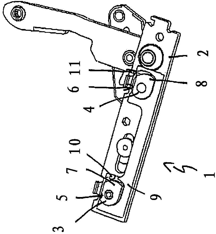
[0027] figure 1 It shows a view from below of a fastening device 1 for fastening a component 2 designed as a corner bearing to a window, door or similar structure, in particular to a fitting channel of a frame profile. The fastening device 1 has two clamping elements 3 , 4 which are held on the component 2 via screws 5 , 6 . In the assembly position shown, the screws 5 , 6 are partially screwed into the clamping elements 3 , 4 . It can be seen that the clamping elements 3 , 4 , which are rotatable about the screw axes of the screws 5 , 6 , are designed eccentrically. The clamping elements 3 , 4 each have a clamping section 7 , 8 .

[0028] The fastening device 1 also has a clamping piece 9 configured as a clamping strip. The clamping block 9 has two clamping element recesses 10 , 11 in which the clamping elements 3 , 4 are arranged.

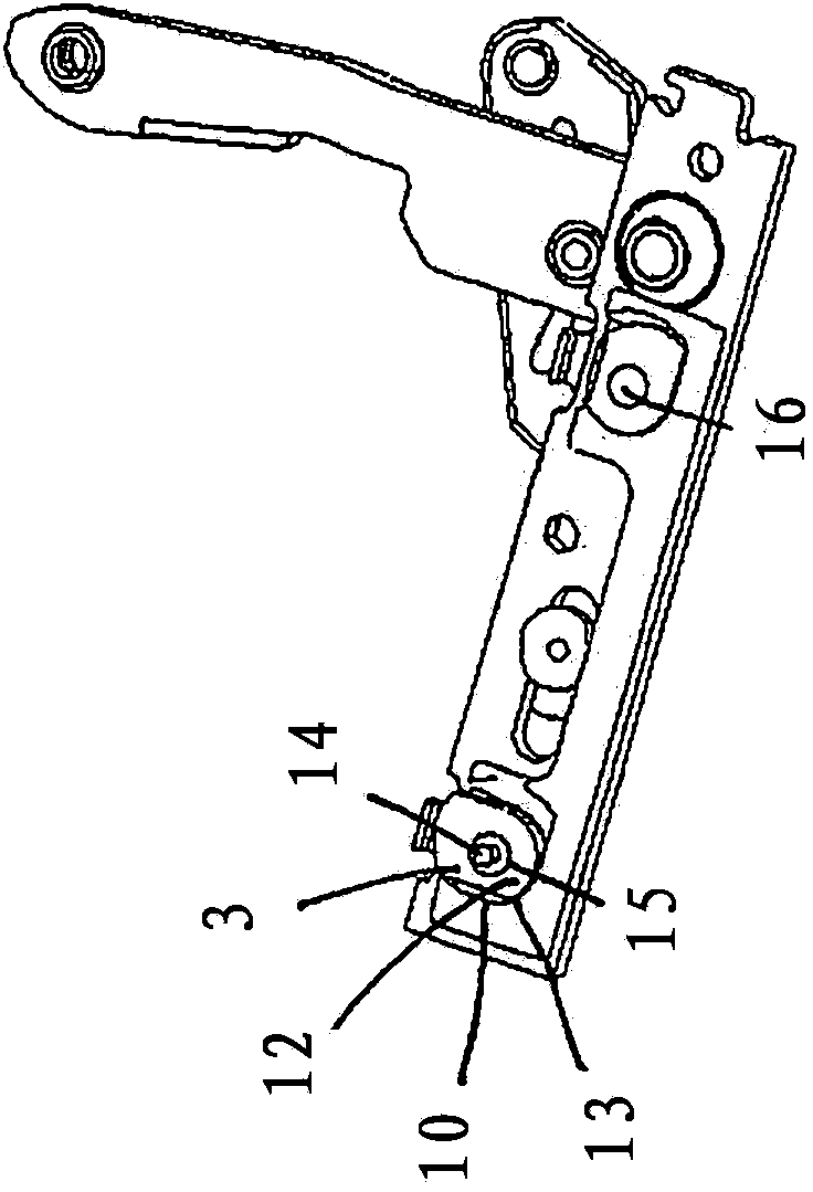
[0029] basically corresponds to figure 1 of the icon figure 2 In the illustration shown, the clamping element 3 has been rotated by 90° a...


PUM


Abstract

The invention relates to a fastening assembly (1) for fastening a component (2) to a groove (21) of a window, a door, or the like by means of a clamping element (3, 4), into which a screw (5, 6) is screwed, which screw passes through the component (2), wherein the screw (5, 6) has a form-closure and / or force-closure end for producing a form closure and / or force closure with the groove.

Description

technical field [0001] The invention relates to a fastening device for fastening a component to a recess, in particular an undercut, of a window, door or similar structure, said fastening device having a clamping element into which a bolt passing through the component is screwed element. Background technique [0002] For fastening components, in particular fittings, to profiles with undercut grooves, such as window or door frames, it is known to use slides, which are introduced into the groove and then rotated, The slider thus acts from behind on the undercut undercut (also called slot stop or slot stop). [0003] A swing hinge is known from DE 20113607 U1, which is fastened to the profile via slot nuts. Bolts are screwed into the slider. As a result, the slide is moved in the direction of the component to be fastened, so that the slot stop is clamped between the slide and the component. [0004] However, it cannot be completely avoided in this fastening method that the ...

Claims


Application Information

Patent Timeline
IPC IPC(8): E05D5/02
CPCE05D5/0238E05D15/30E05D15/5214E05D15/5211E05Y2900/148E05Y2900/132
Inventor M·西格勒M·贡泽尔
Owner ROTO FR
Features
  • Generate Ideas
  • Intellectual Property
  • Life Sciences
  • Materials
  • Tech Scout
  • Unparalleled Data Quality
  • Higher Quality Content
  • 60% Fewer Hallucinations
Learn More