Full-automatic electric cooker
An electric rice cooker, fully automatic technology, applied to cooking utensils, household utensils, applications, etc., can solve the problem of easy adhesion of rice grains on the inner wall of the rice washing bin, difficulty in opening the lid of the rice cooker, and complicated structure of the rice washing device And other problems, to achieve the effect of stable rotation, easy cleaning and convenient operation
- Summary
- Abstract
- Description
- Claims
- Application Information
AI Technical Summary
Problems solved by technology
Method used
Image

Examples
Embodiment Construction
[0036] The present invention will be described in detail below in conjunction with accompanying drawing and embodiment:
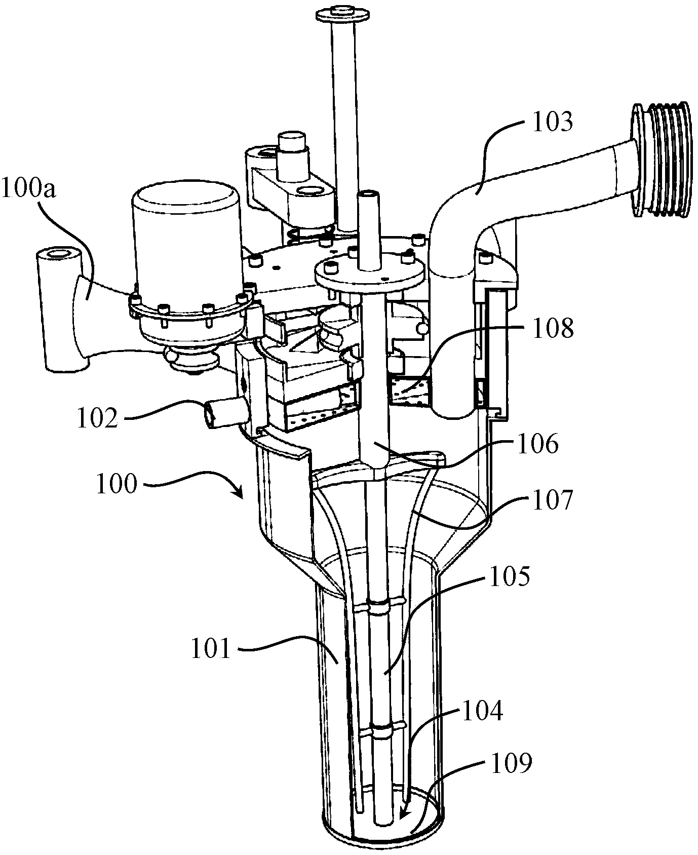
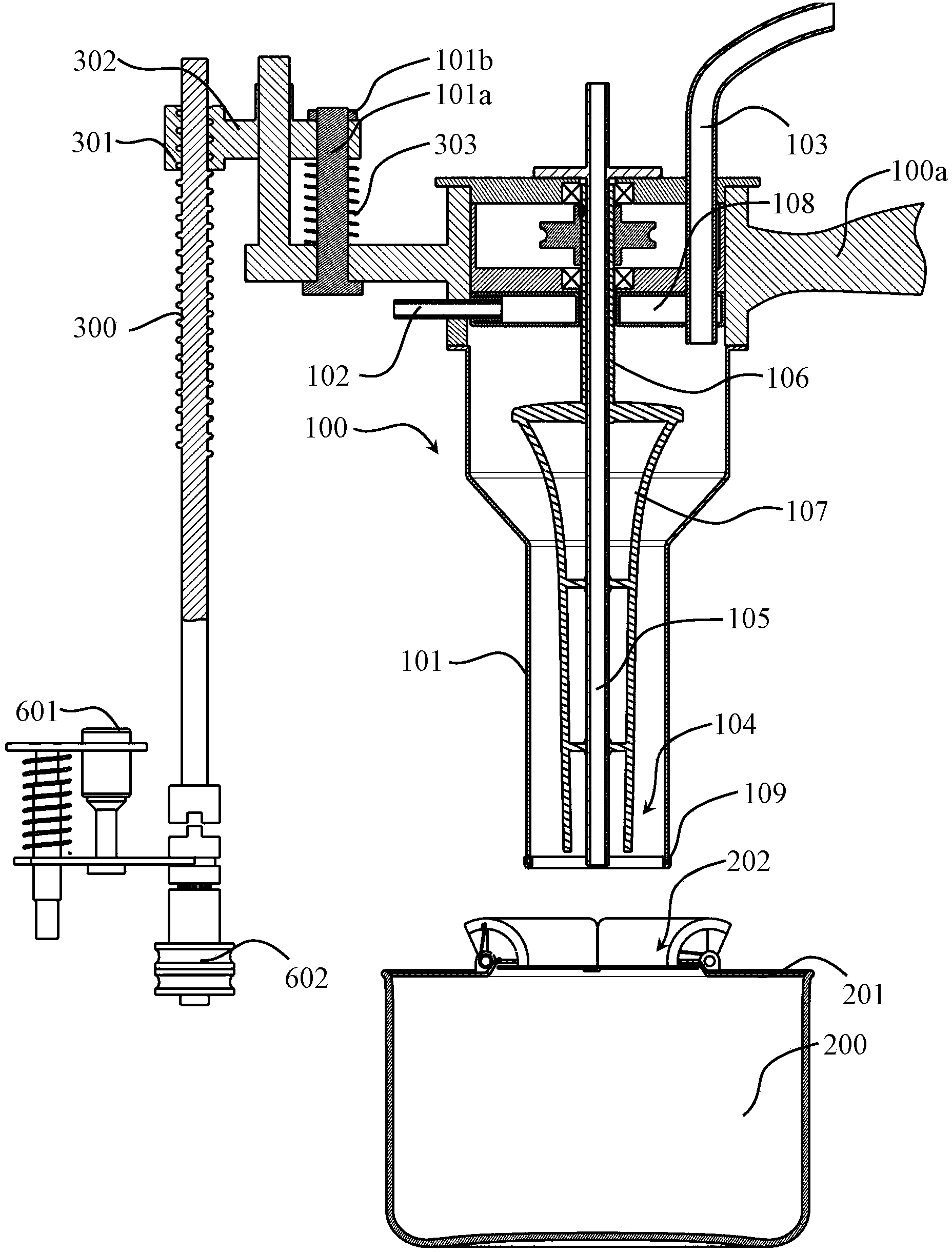
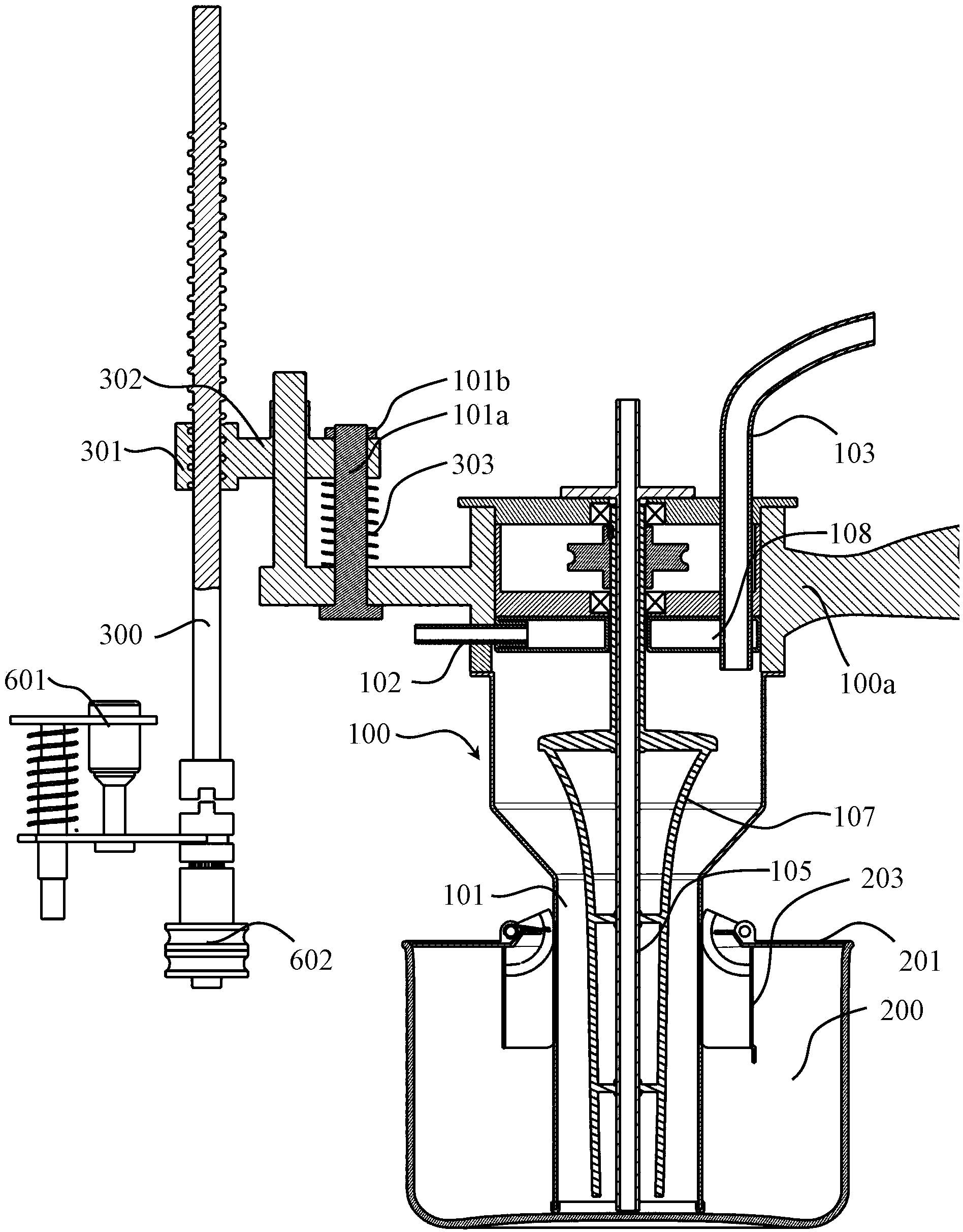
[0037]The fully automatic electric rice cooker in this embodiment includes a rice washing device 100 and an electric rice cooker body 200, and the rice washing device 100 includes a stirrer, a cylindrical rice washing bin 101 and a device for controlling the up and down movement of the rice washing bin 101 The first lifting mechanism, the first lifting mechanism includes a first screw 300 arranged vertically, a first nut 301 threadedly engaged with the first screw 300 and a cantilever 302 fixedly connected with the first nut 301 , adopt the lead screw mechanism that the first lead screw 300 and the first nut 301 are formed to control the lifting of the rice washing bin, which has the advantages of simple structure, stable movement, and convenient control. In this embodiment, the first lead screw 300 The rotation is controlled by a motor 600; the lifting mec...
PUM
 Abstract
Description
Claims
Application Information
 - R&D
- Intellectual Property
- Life Sciences
- Materials
- Tech Scout
- Unparalleled Data Quality
- Higher Quality Content
- 60% Fewer Hallucinations
Browse by: Latest US Patents, China's latest patents, Technical Efficacy Thesaurus, Application Domain, Technology Topic, Popular Technical Reports.
© 2025 PatSnap. All rights reserved.Legal|Privacy policy|Modern Slavery Act Transparency Statement|Sitemap|About US| Contact US: help@patsnap.com