Wedge side-shaping die

A technology of side shaping and wedge, applied in the direction of forming tools, manufacturing tools, metal processing equipment, etc., can solve the problems of outer surface deformation, difficult outer surface, etc., to improve quality, avoid deformation of parts, and avoid scratches. The effect of the outer surface of the piece

Inactive Publication Date: 2014-05-28
CHERY AUTOMOBILE CO LTD
View PDF10 Cites 16 Cited by
  • Summary
  • Abstract
  • Description
  • Claims
  • Application Information

AI Technical Summary

Problems solved by technology

[0007] The invention designs a wedge side shaping die, which solves the technical problems as follows: (1) The structure of the wedge side shaping die with a traditional pressing core, but it is difficult to ensure that the part is associated with the side shaping during side shaping The outer surface of the part is fully compressed, and the outer surface of the part associated with side shaping is stretched during side shaping, causing the outer surface to deform

Method used


Image

  • Wedge side-shaping die
  • Wedge side-shaping die
  • Wedge side-shaping die

Examples


Embodiment 1

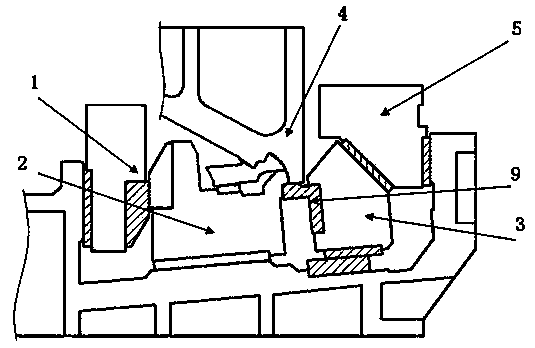
[0040] Example 1: By Figure 5 As shown, it is a schematic diagram of the mold retracting state of the present invention. At this time, the first oblique wedge driving block 1 and the second oblique wedge driving block 5, the rotary sub-binder core 6 and the female binder core 7 are all in a non-working state.

[0041] When the mold moves downward to work, the following describes the order in which the working parts involved in the present invention start to work:

[0042] The first stage: such as Image 6 Shown is the state in which the first oblique wedge drive block 1 of the present invention has completed driving the punch 2. In this process, the mold drives the first oblique wedge drive block 1 to move downward to drive the punch 2 to move to the predetermined position for workpiece processing After that, the first oblique wedge driving block 1 continues to move downward with the mold, and the punch 2 no longer moves in the oblique wedge working direction, and is in the residen...

Embodiment 2

[0048] by Picture 10 Shown is a schematic diagram of the retreat state of the mold of the present invention. At this time, the first oblique wedge driving block 21 and the second oblique wedge driving block 25, the sliding wedge-type sub-pressing core 26 and the mother pressing-material core 27 are all in a non-working state .

[0049] When the mold moves downward to work, the following describes the order in which the working parts involved in the present invention start to work:

[0050] The first stage: such as Picture 11 Shown here is the state where the first oblique wedge drive block 21 of the present invention has completed driving the punch 22. During this process, the mold drives the first oblique wedge drive block 21 to move downward to drive the punch 22 to move to a predetermined position for workpiece processing After that, the first oblique wedge driving block 21 continues to move downward with the mold, and the convex mold 22 no longer moves in the direction of the...


PUM


Abstract

The invention relates to a wedge side-shaping die which comprises a first wedge driving block (1), male dies (2 and 22), wedge sliders (3 and 23), second wedge driving blocks (5 and 25), auxiliary pressing cores (6 and 26), primary pressing cores (7and 27) and side shaping female die inserts (9 and 29). The first wedge driving block (1) drives the male dies (2 and 22) to move, the second wedge driving blocks (5 and 25) drive the auxiliary pressing cores (6 and 26) and the wedge sliders (3 and 23) to move, workpieces are arranged on the male dies (2 and 22), the auxiliary pressing cores (6 and 26) press laterally along the direction of wedge side-shaping, and the primary pressing cores (7 and 27) press along the perpendicular direction. The wedge side-shaping die is characterized in that stress springs (8 and 28) of the auxiliary pressing cores (6 and 26) are fixed on the wedge sliders (3 and 23), the auxiliary pressing cores (6 and 26) laterally press along the second wedge driving blocks (5 and 25) through the springs (8 and 28) so as to guarantee that the workpieces are sufficiently pressed during side shaping, and deformation of the workpieces is effectively avoided.

Description

Technical field [0001] The invention relates to the technical field of cold stamping of automobile covering parts, in particular to a novel composite wedge die structure. Specifically, especially when used for side shaping of the outer cover, and the shape of the outer surface of the shaping related parts is steep, a rotary composite core is used to ensure that the surface of the part is fully compressed and to prevent surface scratches. Background technique [0002] Auto body panel stamping die is the most demanding and most difficult die in auto body manufacturing, and it is also a rapidly developing cold stamping process equipment in my country's electromechanical parts manufacturing. The quality of car outer coverings directly affects the appearance quality of the whole car. [0003] Take the side wall outer panel of a certain vehicle as an example, such as figure 1 with figure 2 As shown, the angle θ at the forming point B of the contact section where the side panel of the v...

Claims


Application Information

Patent Timeline
Patent Type & Authority Applications(China)
IPC IPC(8): B21D37/10
Inventor 黄祥坤杨雪梅
Owner CHERY AUTOMOBILE CO LTD
Why Eureka
Try Eureka