Self-adjusting welding wire for welding application

A self-adjusting, welding wire technology used in the field of alignment of materials and objects

Inactive Publication Date: 2014-05-28
GM GLOBAL TECH OPERATIONS LLC
View PDF10 Cites 9 Cited by
  • Summary
  • Abstract
  • Description
  • Claims
  • Application Information

AI Technical Summary

Problems solved by technology

Bending of the wire and misalignment of the wire with the workpiece can also cause problems in other processes, such as when the wire is threaded through a hole or when the wire is being welded together

Method used


Image

  • Self-adjusting welding wire for welding application
  • Self-adjusting welding wire for welding application
  • Self-adjusting welding wire for welding application

Examples


Embodiment Construction

[0051] Exemplary, non-limiting embodiments are described in detail below.

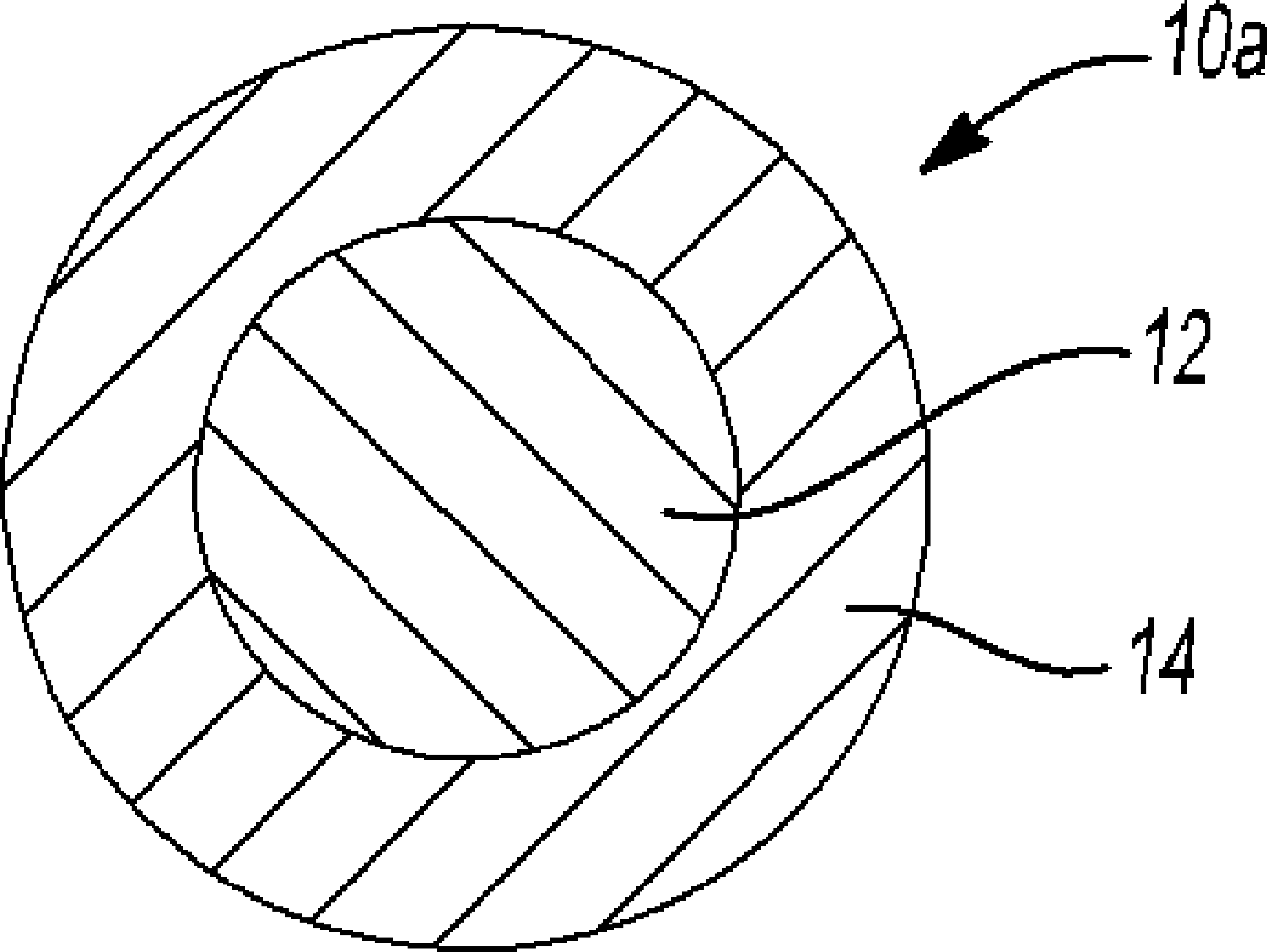
[0052] Figure 1a and 1b Two example configurations for self-adjusting welding wires are shown. The self-regulating welding wire 10a has a core 12 of a metal or metal alloy suitable for use as a bonding material, such as a welding or filler material, and a cladding or outer layer 14 of a shape memory alloy. Figure 1a The outer layer 14 is the layer or cladding that continuously surrounds the periphery of the core 12 . Layer 14 is generally cylindrical or tubular surrounding and adjacent the outer surface of core 12 . The self-regulating welding wire 10b also has a core 12 of metal or metal alloy suitable for use as bonding material, eg welding or filler material, but the outer layer 16 of shape memory alloy is a layer that does not completely surround the periphery of said core 12 . In various embodiments, while not completely covering the periphery of core 12, outer layer 16 may be more Figure 1b...


PUM

PropertyMeasurementUnit
phase transition temperatureaaaaaaaaaa
diameteraaaaaaaaaa
diameteraaaaaaaaaa

Abstract

The invention relates to a self-adjusting welding wire for welding application, and particularly discloses a self-adjusting welding wire, a method for manufacturing the self-adjusting welding wires, a heating bonding process (such as gas metal arc welding or laser beam braze welding) and other processes using the self-adjusting welding wires. The welding wire is provided with a metal or metal alloy core suitable for serving as a bonding material in the bonding process and an outer layer of shape memory alloy, and the outer layer such as one or multiple longitudinal straps can encircle the external portion of the core continuously or discontinuously. The shape memory alloy of the self-adjusting welding wire is 'trained' to be in a straight welding wire shape in austenite. In the processes using the self-adjusting welding wires, bent end portions of the self-adjusting welding wires are straightened by heating the self-adjusting welding wires to the temperature higher than the austenite phase transition temperature of the shape memory alloy.

Description

technical field [0001] The present invention relates to methods of welding and joining and materials and articles for use in such methods. In another aspect, the present invention relates to procedures relating to alignment of welding wires and the like. Background technique [0002] This section provides information that may be helpful in understanding the present invention but is not necessarily prior art. [0003] Gas metal arc welding (GMAW), often also referred to as metal inert gas (MIG) welding, is an arc welding process using a continuous, consumable welding or filler wire as the electrode. In metal inert gas arc welding, a consumable wire electrode made of a conductive metal such as a copper alloy is passed through the welding torch or torch and out of the torch contact tip. An electrical potential applied between the contact tip and the metal workpiece to be welded results in a current in the wire that supports the arc between the wire end and the metal workpiece...

Claims


Application Information

Patent Timeline
Patent Type & Authority Applications(China)
IPC IPC(8): B23K35/12B23K35/24B23K9/173
CPCB23K35/0272B23K35/24B23K9/173B23K35/286B23K35/302B23K35/3033B23K35/3066B23K35/325B23K35/0266C22C37/00C22C38/04C22C38/08C22C38/18B23K35/30B23K35/32B23K35/0255B23K35/0261B23K35/22
Inventor 张婧王培中杨上陆
Owner GM GLOBAL TECH OPERATIONS LLC
Why Eureka
Try Eureka