Angular deflection apparatus for use in confined spaces and method of use

a technology of angular deflection apparatus and confined space, which is applied in the direction of contraceptive devices, catheters, therapy, etc., can solve the problem of relatively high cost of nickel-titanium alloys

Inactive Publication Date: 2005-08-25
TRIMEDYNE
View PDF7 Cites 146 Cited by
  • Summary
  • Abstract
  • Description
  • Claims
  • Application Information

AI Technical Summary

Benefits of technology

[0023] Specifically, the present invention is a tissue affecting means consists of a tube with a distal end portion made of a superelastic, nickel/titanium memory metal alloy which has been heat-treated to retain a desired curved shape. The tube is moveably disposed within and constrained by a sleeve or by the instrument channel of an endoscope, both of which are stronger, that is stiffer than the distal end portion of the tube. When t

Problems solved by technology

Nickel-titanium alloys a

Method used


Image

  • Angular deflection apparatus for use in confined spaces and method of use
  • Angular deflection apparatus for use in confined spaces and method of use
  • Angular deflection apparatus for use in confined spaces and method of use

Examples


Embodiment Construction

[0034] The above described drawing figures illustrate the invention in at least one of its preferred embodiments, which is further defined in detail in the following description. Those having ordinary skill in the art may be able to make alterations and modifications in the present invention without departing from its spirit and scope. Therefore, it must be understood that the illustrated embodiments have been set forth only for the purposes of example and that they should not be taken as limiting the invention as defined in the following.

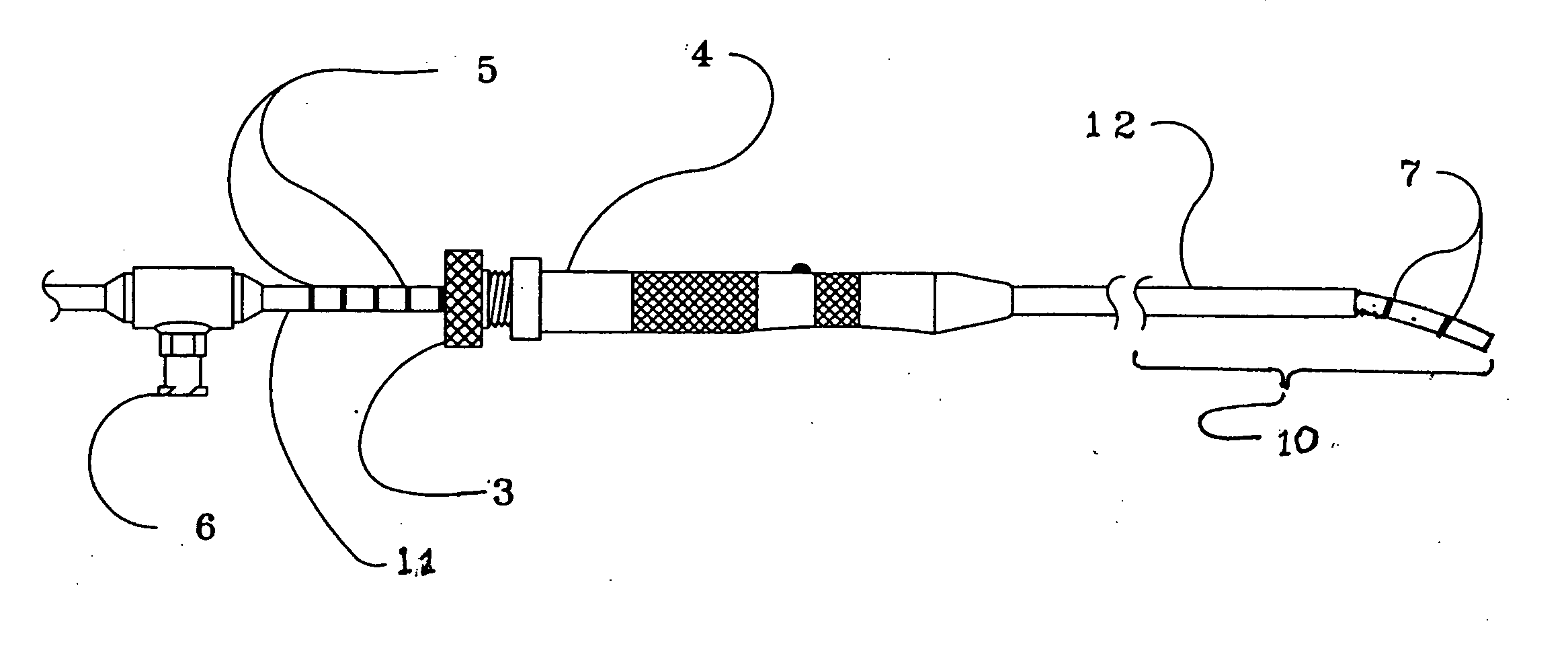
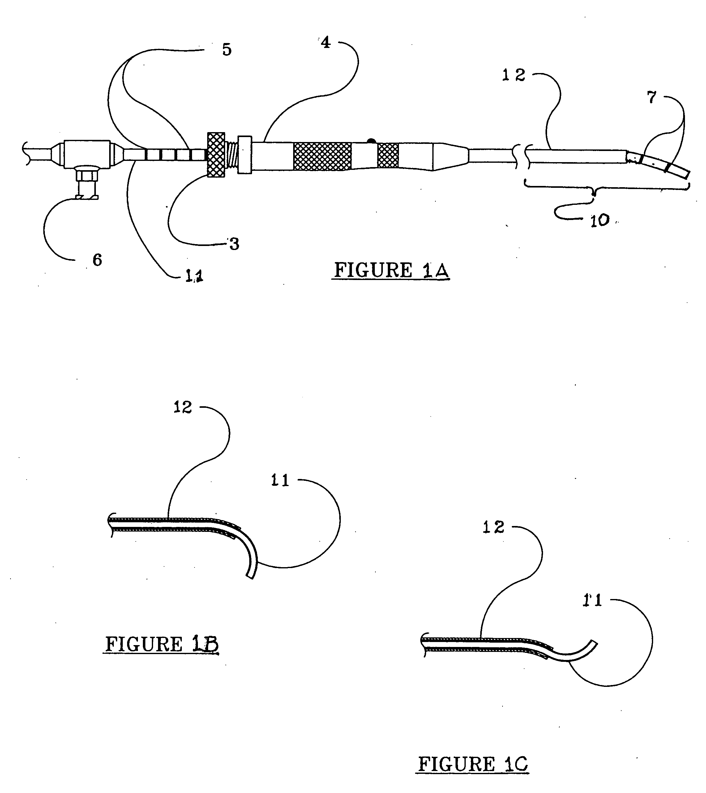
[0035]FIG. 1A illustrates the present invention with the distal portion identified by bracket 10. Relatively elastic member, tube 11, preferably has a fixed bend at its distal end, and is moveably extendable from relatively inelastic member, sleeve 12, which extends distally from handpiece 4. Tube 11 extends through gripping mechanism 3 in the proximal end of hand piece 4, and through handpiece 4 and sleeve 12, which enables convenient and easy us...


PUM


Abstract

A tube having a distal end portion made of a curved, flexible, shape retentive material such as superelastic, nickel-titanium memory metal alloy which has been heat-treated to retain a desired curved shape. The tube translates within and is constrained by a rigid sleeve, which may alternately be an instrument channel of an endoscope. When the distal end portion of the tube is extended from the sleeve, it returns to its original curved shape. Markings about the proximal and, or distal end portions of the tube enable the operator to know to what extent the distal end portion of the tube has been extended from the sleeve even when the distal end portion of the tube is not visible. The tube may be used for supporting and activating a cutting, abrading, coagulating, shrinking, or vaporizing device that is brought near or into contact with a tissue surface.

Description

BACKGROUND OF THE INVENTION [0001] 1. Incorporation by Reference [0002] Applicant(s) hereby incorporate herein by reference, any and all U.S. patents, U.S. patent applications, and other documents and printed matter cited or referred to in this application. [0003] 2. Field of the Invention [0004] This invention relates generally to apparatus for reaching confined and difficult areas with a work tool and more particularly to such an apparatus capable of manipulation to selected angles and positions when the therapeutic portion of the tool is fully or partially hidden from view. [0005] 3. Description of Related Art [0006] The following defines the present state of this field: [0007] Cutting, removing, coagulating or shrinking tissue in a confined space, such as in a: foraminal space in a spinal column, duct, surgically created passageway, or hollow organ, poses a significant difficulty to a surgeon. Such surgery is conducted using, for instance, a rotating burr, a shaver, or a radio f...

Claims


Application Information

Patent Timeline
IPC IPC(8): A61B17/00A61B17/22A61B17/32A61B18/02A61B18/04A61B18/14A61B18/18A61B18/24A61F7/00A61F7/12A61M1/00A61N2/00
CPCA61B17/32002A61B17/320783A61B18/0218A61B2217/005A61B18/24A61B2017/003A61B2017/00867A61B18/1492
Inventor LOEB, MARVIN P.YEIK, GLENN D.CRAWFORD, L. DEAN
Owner TRIMEDYNE
Why Eureka
Try Eureka