A clutch removal device

A dismantling device and clutch technology, applied to hand-held tools, manufacturing tools, etc., can solve the problems of difficulty in installation and disassembly, damage to the clutch shaft, and high requirements on assembly accuracy, and achieve the effects of satisfying disassembly requirements, simple structure, and convenient use.

Inactive Publication Date: 2017-03-29
彭生辉
View PDF7 Cites 0 Cited by
  • Summary
  • Abstract
  • Description
  • Claims
  • Application Information

AI Technical Summary

Problems solved by technology

[0003] In the process of disassembling the clutch, due to the tight connection between the clutch shaft and the center hole of the clutch, it is difficult to install and disassemble, and the clutch cylinder liner is also installed outside the clutch. Due to the higher assembly accuracy requirements inside the clutch, It is impossible to dismantle the cylinder liner for installation and disassembly. In this way, the disassembly personnel can only hard install and dismantle when installing and dismounting, which may easily cause damage to the clutch shaft. At this stage, there are almost no disassembly devices specially used for automobile clutches. After extensive searching, there is no Find the ideal technical solution

Method used


Image

  • A clutch removal device
  • A clutch removal device

Examples


Embodiment Construction

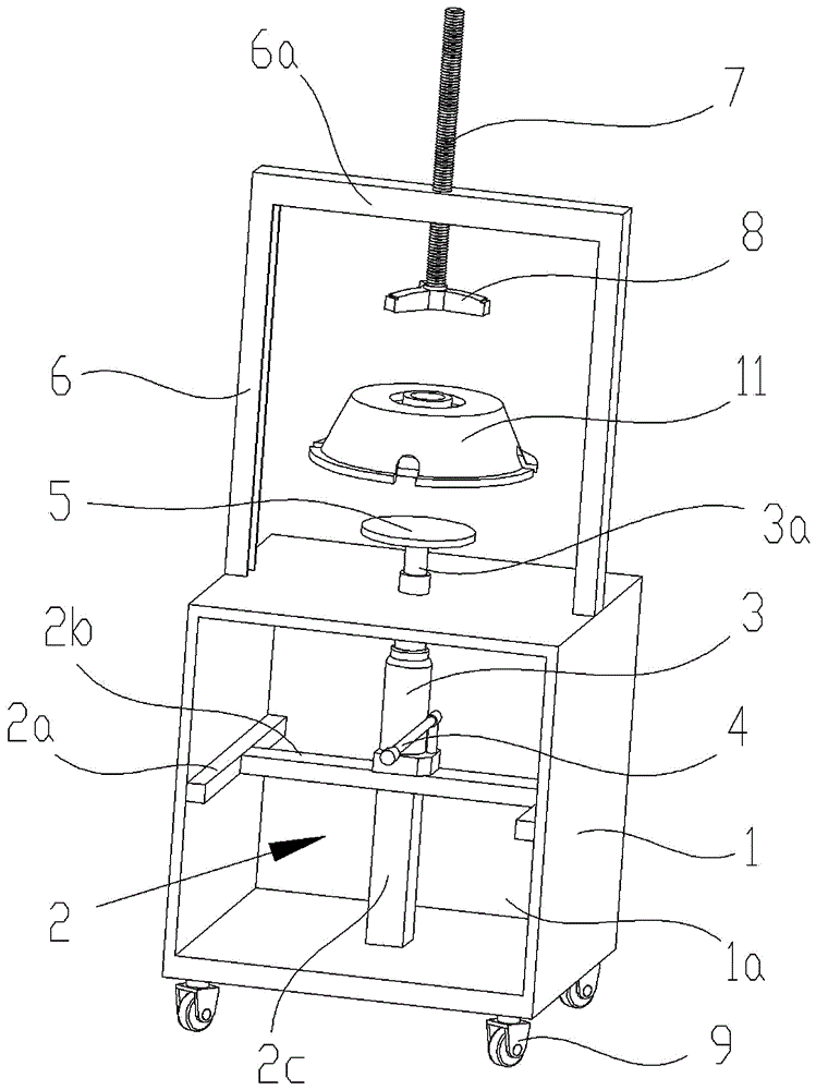
[0014] Such as figure 1 As shown, a clutch disassembling device provided by the present invention is characterized by comprising: a box body 1, which is a square box with an open structure on one side, and a bracket 2 is connected in the cavity 1a of the box body 1. A universal wheel 9 is respectively connected to the four corners at the bottom of the box 1, two uprights 6 are welded symmetrically at the center of the top of the box 1, and a cross beam 6a is connected to the top of the two uprights 6, and the center of the cross beam 6a is provided One screw hole.

[0015] The bracket 2 includes two fixed rods 2a. The fixed rods 2a are respectively welded horizontally and symmetrically on the inner side of the two symmetrical side walls of the box 1, and a connecting rod 2b is welded between the two fixed rods 2a. A support rod 2c is welded to the bottom of 2b through the center, and the support rod 2c is welded to the bottom plate of the box 1, and a hydraulic pump 3 is also con...


PUM


Abstract

The invention relates to a device for demounting clutches. The device is characterized by comprising a box body (1); a support (2) is connected into a cavity (1a) of the box body (1), a hydraulic pump (3) is connected to the support (2), a piston rod (3a) of the hydraulic pump (3) penetrates through the upper side face of the box body (1), a top tray (5) is connected to the top end of the piston rod (3a), two vertical columns (6) are connected to the box body (1), a cross beam (6a) is connected between the two vertical columns (6), a push rod (7) is connected to the cross beam (6a), and a pressing block (8) is connected to the bottom of the push rod (7) and corresponds to and is matched with the top tray (5). The device for demounting the clutches has the advantages that the device is simple in structure and convenient to use, and can meet the requirement for demounting the clutches of different sizes and models due to the fact that the push rod can move up and down along the cross beam.

Description

Technical field [0001] The invention relates to a repair tool for automobile parts, in particular to a clutch disassembly device. Background technique [0002] With the development of society, cars have become an indispensable means of transportation in the modern transportation industry. With the increase in the number of cars, car repair has become a major industry in today’s society. Most car repairs need to be carried out first. The parts to be replaced or repaired are removed and removed. [0003] In the process of disassembling the clutch, due to the tight connection between the clutch shaft and the center hole of the clutch, it is difficult to install and dismantle, and the clutch cylinder liner is also installed on the outside of the clutch. Due to the higher requirements for assembly accuracy inside the clutch, It is impossible to remove the cylinder liner for installation and disassembly, so the disassembly personnel can only install and dismantle hard during installatio...

Claims


Application Information

Patent Timeline
Patent Type & Authority Patents(China)
IPC IPC(8): B25B27/02
CPCB25B27/0064
Inventor 彭生辉张志刚王远张杰刘青掌
Owner 彭生辉
Why Eureka
Try Eureka