Flexible belt dismounting device

A technology for dismantling devices and belts, which is applied in the direction of hand-held tools and manufacturing tools, can solve problems such as work-related accidents, time-consuming and labor-intensive belt disassembly, and achieve the effects of avoiding disability, reducing weight, and eliminating potential safety hazards

Pending Publication Date: 2021-06-11
曲茂绪
View PDF0 Cites 0 Cited by
  • Summary
  • Abstract
  • Description
  • Claims
  • Application Information

AI Technical Summary

Problems solved by technology

[0004] The invention provides a flexible belt dismounting device aiming at the problems in the prior art that the disassembly of the belt is time-consuming and labor-intensive, and is likely to cause work-related accidents.

Method used


Image

  • Flexible belt dismounting device
  • Flexible belt dismounting device
  • Flexible belt dismounting device

Examples


Embodiment 1

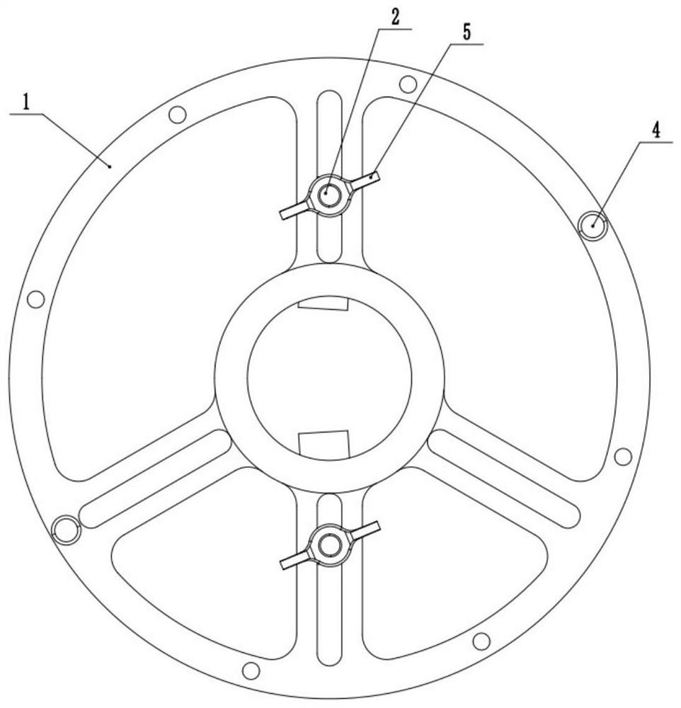
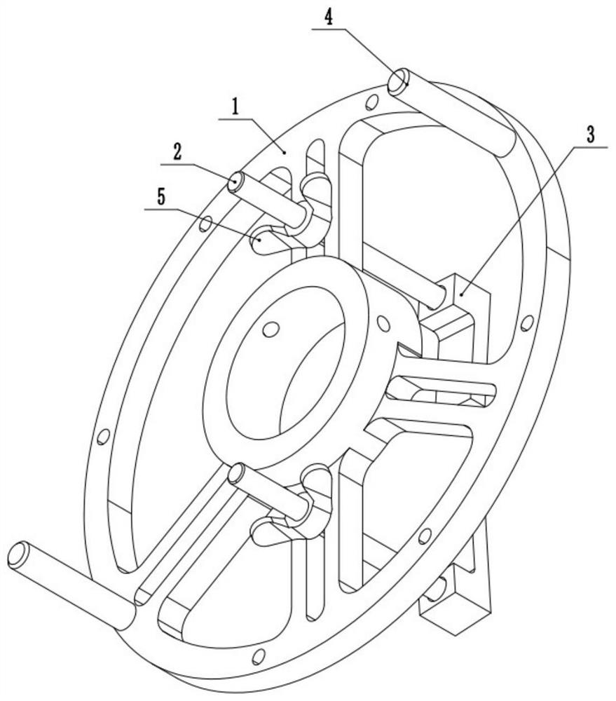
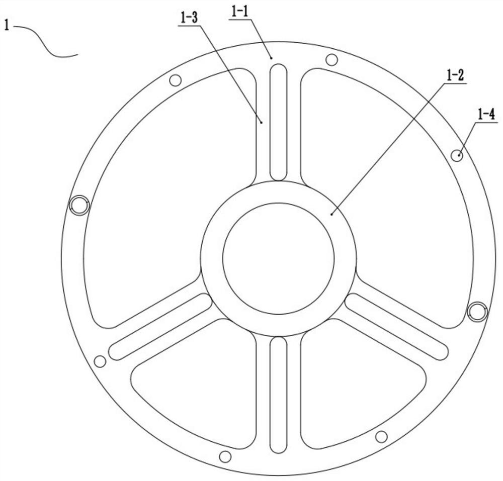
[0036] refer to Figure 1 to Figure 5 , a flexible belt removal device, including a runner body 1 and a tension rod 2, the runner body 1 includes an outer rim 1-1 and an inner rim 1-2, and the outer rim 1-1 and the inner rim There are several ribs 1-3 arranged in the circumferential direction between 1-2, an operating rod 4 is installed on the outer rim 1-1, an installation groove is arranged on the ribs 1-3, and the tension rod 2 is inserted into the installation groove, and one end of the tension rod 2 is provided with a fastener 5, and the other end is provided with a tension plate 3.

[0037] The installation groove is elongated, the length of the installation groove ranges from R65mm to R180mm, and the width of the installation groove matches the tension rod 2 . According to the size of the rib plate of the pulley, the position of the tension rod 2 in the installation groove can be adjusted, so that the tension plate 3 can be smoothly fixed on the rib plate of the pulley...

Embodiment 2

[0050]refer to Figure 6 and Figure 7 , is different from Embodiment 1 in the structure connected with the pulley, and the rest are the same as Embodiment 1.

[0051] The tension rod 2 is removed, and a shaft sleeve 6 is placed in the inner rim 1-2, a keyway 6-1 is provided on the inner side wall of the shaft sleeve 6, and a keyway 6-1 is provided on the outer side wall of the shaft sleeve 6. There is a groove 6-2, and the inner rim 1-2 is provided with a fixing hole corresponding to the groove 6-2, and the fixing hole is used to accommodate the top wire 8.

[0052] A positioning hole 6-3 is provided on the side wall of the shaft sleeve 6, and a positioning member is provided in the positioning hole 6-3.

[0053] Optionally, the positioning member may be a bolt or a screw.

[0054] There are three grooves 6 - 2 , and the three grooves 6 - 2 are evenly distributed on the outer wall of the sleeve 6 in the circumferential direction, and the grooves 6 - 2 extend along the leng...


PUM

PropertyMeasurementUnit
Lengthaaaaaaaaaa

Abstract

The invention relates to the technical field of belt dismounting, in particular to a flexible belt dismounting device. The flexible belt dismounting device comprises a rotating wheel body and tensioning rods, the rotating wheel body comprises an outer wheel ring and an inner wheel ring, a plurality of rib plates arranged in the circumferential direction are arranged between the outer wheel ring and the inner wheel ring, an operation rod is installed on the outer wheel ring, and mounting grooves are formed in the rib plates. The tensioning rods are inserted into the mounting grooves, fasteners are arranged at one ends of the tensioning rods, and tensioning plates are arranged at the other ends of the tensioning rods. A belt pulley is fixed through the tensioning rods and the tensioning plates, the rotating wheel body is rotated through the operation rod, so that the belt pulley is driven to rotate, a hand of a maintainer is prevented from making direct contact with a meshing point of the belt pulley when the maintainer replaces a belt, potential safety hazards are eliminated, the risk level is reduced, and disability and other safety accidents are avoided; the tensioning rods are inserted into the mounting grooves, so that the tensioning rods are supported and guided, and the operation is simpler; and the rib plates are arranged between the inner wheel ring and the outer wheel ring, the weight of the rotating wheel body can be reduced, and mounting and dismounting are convenient.

Description

technical field [0001] The invention relates to the technical field of belt removal, in particular to a flexible belt removal device. Background technique [0002] Because the belt has the advantages of stable transmission operation, low noise, small vibration, simple structure, and convenient adjustment, it is used in many machining occasions to transmit power. The fan belt needs to be repaired or replaced due to wear after a period of use. At present, due to the lack of special tools for removing fan belts, most of them rely on operators to replace them by hand. When the operator removes the belt by hand, it is generally necessary to turn the pulley with one hand and pull the belt with the other hand. The hands of the personnel are caught between the belt and the pulley, causing safety accidents such as hand crushing or permanent hand injury. [0003] Although there are also some belt removal tools in the prior art, the existing belt removal tools can only remove a cert...

Claims


Application Information

Patent Timeline
IPC IPC(8): B25B27/00
CPCB25B27/00
Inventor 曲茂绪刘涛赵启阳张立新李竹青
Owner 曲茂绪
Why Eureka
Try Eureka