Construction device, construction system and construction method for disengaging type pile plate structure
A pile-slab structure and construction device technology, applied in the field of geotechnical engineering, can solve the problems of affecting the smoothness of the track, the difficulty of effectively dismantling and reusing formwork and support columns, and increasing project investment.
- Summary
- Abstract
- Description
- Claims
- Application Information
AI Technical Summary
Problems solved by technology
Method used
Image
Examples
Embodiment 1
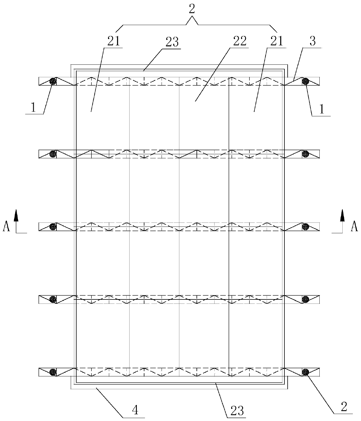
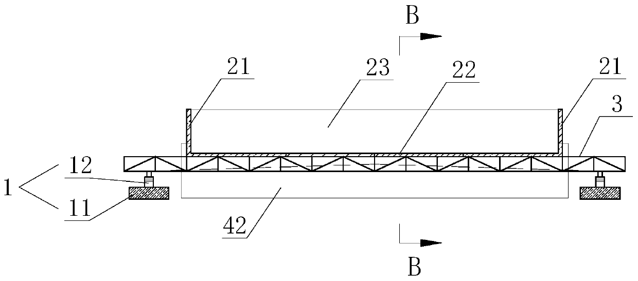
[0071] like Figure 1-7 As shown, a construction device for a void-type pile-slab structure described in this embodiment includes a base 11, a jack 12, a truss-type load-bearing beam 3, an L-shaped steel formwork 21, a plane steel formwork 22, and a U-shaped block plate 23. The base 11 is poured with concrete and placed in the cutting foundation 5; the jack 12 and the truss-type load-carrying beam 3 are sequentially arranged on the base 11 from bottom to top; the L-shaped steel formwork 21 and the plane steel formwork 22 are vertically erected along the line On the truss load beam 3 ; the U-shaped baffle 23 is placed on the joist 42 .
[0072] The truss-type load-bearing beam 3 is made of segmental assembled rigid structure, and the length of each segmental rigid truss is not greater than the distance from the edges on both sides of the load-bearing plate 43 to the toe of the cutting slope. The function of the truss-type load-bearing beam 3 is to carry the L-shaped steel for...
Embodiment 2
[0078] like Figure 1-7 As shown, a construction device for a hollow pile-slab structure described in this embodiment differs from Embodiment 1 in that it includes a construction formwork 2 for pouring a bearing plate 43, and at least two truss-type The load-carrying beam 3 is arranged at the bottom of the construction formwork 2 for stably supporting the construction formwork 2. The construction formwork 2 is a box-shaped member with an open top, and the construction formwork 2 is set as a L-shaped steel formwork 21. The structural member spliced by plane steel formwork 22 and U-shaped baffle 23, after the loading plate 43 is poured, the construction formwork 2 can be split into L-shaped steel formwork 21, plane steel formwork 22 and U-shaped baffle 23, so that the effective dismantling of the construction formwork 2 can be realized very simply, and the situation that the foundation uplift works and transmits the load-bearing plate 43 through the construction formwork 2 doe...
Embodiment 3
[0090] like Figure 8-10 As shown, a construction system described in this embodiment includes a foundation 5 and the construction device as described in Embodiment 1 or 2, the base 11 is a structural member formed by pouring concrete, and the base 11 is arranged on In the foundation 5 , all the truss-type load-bearing beams 3 are longitudinally spaced along the line, and the U-shaped baffles 23 are placed on the joists 42 .
[0091] During installation, since the bearing plate 43 extends longitudinally along the line, all the truss-type load-bearing beams 3 are distributed longitudinally along the line to facilitate better disassembly in the later stage. Good strength, avoiding the settlement of the base 11 during the jacking process of the jack 12, causing the truss-type load-bearing beam 3 to tilt and slide. The U-shaped baffle 23 is placed on the joist 42, relying on the joist that has been made 42 to support and position the U-shaped baffle 23, so as to ensure the precis...
PUM
 Abstract
Description
Claims
Application Information
 - R&D
- Intellectual Property
- Life Sciences
- Materials
- Tech Scout
- Unparalleled Data Quality
- Higher Quality Content
- 60% Fewer Hallucinations
Browse by: Latest US Patents, China's latest patents, Technical Efficacy Thesaurus, Application Domain, Technology Topic, Popular Technical Reports.
© 2025 PatSnap. All rights reserved.Legal|Privacy policy|Modern Slavery Act Transparency Statement|Sitemap|About US| Contact US: help@patsnap.com


