Manufacturing method for composite spar cap for wind power blade

A technology of composite materials and manufacturing methods, which is applied in the production of main spar caps and the field of composite main spar caps for wind power blades, which can solve the problems of low tensile strength and elastic modulus, easy-to-touch towers with blade tips, and large Increased blade weight and other issues to achieve the effect of increasing toughness and fracture strain performance, reducing the risk of encountering lightning strikes, and improving toughness and fracture strain

Inactive Publication Date: 2014-05-28
SINOMATECH WIND POWER BLADE
View PDF4 Cites 30 Cited by
  • Summary
  • Abstract
  • Description
  • Claims
  • Application Information

AI Technical Summary

Problems solved by technology

[0002] Glass fiber and carbon fiber are two types of fiber reinforcements commonly used in main spar caps for wind power blades. Each has its advantages and disadvantages: carbon fiber has high strength and high modulus, but its elongation is relatively low, usually about 0.5% to 1.5%, and it is brittle. And the price is high; while glass fiber has higher specific strength than aluminum, steel, cement and other materials, and its elongation is relatively large, about 2% to 5%. It is soft and cheap, but its tensile strength and elastic modulus are relatively low. Low
[0003] The above two kinds of fibers used alone in the main spar cap of large wind power blades have the following defects: 1) The domestic production technology of large tow carbon fibers suitable for wind power blade reinforcement is not yet mature, and the cost of simply relying on imports is relatively high; 2) Carbon fiber prepregs exist The resin has a short pot life and high product storage and transportation costs; 3) The diameter

Method used


Image

  • Manufacturing method for composite spar cap for wind power blade
  • Manufacturing method for composite spar cap for wind power blade
  • Manufacturing method for composite spar cap for wind power blade

Examples


Example Embodiment

[0061] Example 1:

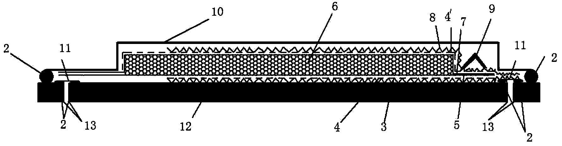
[0062] Such as image 3 , Figure 4 As shown, it is a mixed fiber preform 6 formed by layering a mixed braid 14, wherein the carbon fiber yarn tow is 12K, and the glass fiber yarn is an alkali-free glass fiber yarn.

[0063] If the volume of carbon fiber accounts for 30% of the total volume of the mixed fiber, and the volume of glass fiber accounts for 70% of the total volume of the mixed fiber, it is woven into a mixed braid 14 with an areal density of 830g / m 2 , The thickness is 0.66mm, and 60 layers are covered to form a mixed fiber preform 6 with a maximum thickness of 39.0mm.

[0064] If the volume of carbon fiber accounts for 50% of the total volume of the mixed fiber, and the volume of glass fiber accounts for 50% of the total volume of the mixed fiber, it is woven into a mixed braid 14 with an areal density of 770g / m 2 , The thickness is 0.62mm, and 53 layers are covered to form a mixed fiber preform 6 with a maximum thickness of 32.8mm.

[0065] If the volu...

Example Embodiment

[0068] Example 2:

[0069] Such as image 3 , Figure 5 As shown, it is a mixed fiber preform 6 formed by interlayer mixing of glass fiber fabric 15 and carbon fiber fabric 16. Among them, combined with the fiber length of the corresponding layer in Table 2, the volume fraction of the carbon fiber in the total volume of the mixed fiber is calculated by formula (1).

[0070] If the volume of carbon fiber accounts for 30% of the total volume of the mixed fiber, and the volume of glass fiber accounts for 70% of the total volume of the mixed fiber, the mixed fiber preform 6 with a maximum thickness of 39.0mm is formed by interlayer mixing, and the lower release cloth 5 is required. Overlay forming; the covering steps are as follows: A) First, the density of the first layer is 1200g / m 2 Glass fiber fabric with a thickness of 0.8mm; B) Pave a layer on it with a density of 380g / m 2 The thickness of the carbon fiber fabric is 0.4mm; then, after repeating step A) and step B) for 32 times, l...

Example Embodiment

[0075] Example 3:

[0076] Such as image 3 , Image 6 As shown, it is a mixed fiber preform 6 formed by a sandwich of glass fiber fabric 15 and carbon fiber fabric 16. The surface density of the carbon fiber fabric used is 600g / m 2 , The thickness is 0.55mm, the surface density of glass fiber fabric is 1200g / m 2 , The thickness is 0.8mm. Among them, combined with the fiber length of the corresponding layer in Table 2, the volume fraction of the carbon fiber in the total volume of the mixed fiber is calculated by formula (1).

[0077] If the volume of carbon fiber accounts for 30% of the total volume of the mixed fiber, and the volume of glass fiber accounts for 70% of the total volume of the mixed fiber, the mixed fiber preform 6 with a maximum thickness of 39.0mm is formed in a sandwich mode, and the lower release cloth 5 needs to be first Laying 17 layers of the glass fiber fabric 15 to form a glass fiber preform with a thickness of 13.6 mm, and then laying 22 layers of the car...


PUM

PropertyMeasurementUnit
Thicknessaaaaaaaaaa
Areal densityaaaaaaaaaa
Thicknessaaaaaaaaaa

Abstract

The invention discloses a manufacturing method for a composite spar cap for a wind power blade. The manufacturing method comprises the following steps: 1), paving a double sided tape at the outer end of a vacuum opening of a spar cap mould; 2) paving a bottom diversion net, a lower separation film and a piece of lower demolding cloth on the spar cap mould on the inner side of the double sided tape from bottom up; 3), paving and covering mixed woven fabric, carbon fiber fabric and/or glass fiber fabric on the lower demolding cloth to form a mixed fiber preformed body; 4), paving a piece of upper demolding cloth, an upper separation film and a top diversion net on the mixed fiber preformed body from bottom up in sequence; arranging a runner in the moving direction of fibers and reserving a glue injection opening at the same time; finally, integrally covering the part from the top diversion net to the two ends of the spar cap by using a vacuum bag, and reserving a glue injection opening; 5), vacuumizing the vacuum bag; pouring epoxy resin into the vacuum bag, and then performing solidification molding. The manufacturing method is simple and easy to operate; the overall weight and the manufacturing cost of the wind power blade are reduced, the rigidity is improved, the operation process of the wind power blade is safe and reliable, and popularization and application are facilitated.

Description

technical field [0001] The invention relates to a manufacturing method of a spar cap, in particular to a manufacturing method of a composite spar cap for a wind power blade; it belongs to the technical field of forming a large wind power blade. Background technique [0002] Glass fiber and carbon fiber are two types of fiber reinforcements commonly used in main spar caps for wind power blades. Each has its advantages and disadvantages: carbon fiber has high strength and high modulus, but its elongation is relatively low, usually about 0.5% to 1.5%, and it is brittle. And the price is high; while glass fiber has higher specific strength than aluminum, steel, cement and other materials, and its elongation is relatively large, about 2% to 5%. It is soft and cheap, but its tensile strength and elastic modulus are relatively low. Low. [0003] The above two kinds of fibers used alone in the main spar cap of large wind power blades have the following defects: 1) The domestic prod...

Claims


Application Information

Patent Timeline
IPC IPC(8): B29C70/44
CPCB29C70/443B29C70/546B29L2031/085Y02P70/50
Inventor 薛忠民黄再满陈淳贾智源王海珍宋秋香
Owner SINOMATECH WIND POWER BLADE
Why Eureka
Try Eureka