
Transmission device of CNC chain automatic printing machine

A technology for automatic printing machines and transmission devices, applied in printing machines, rotary printing machines, screen printing machines, etc., can solve problems such as complex structures, achieve good printing effects, improve efficiency, and prevent deformation

Active Publication Date: 2016-01-20
ZHEJIANG DONGHE PRINTING PACKAGING CO LTD
View PDF6 Cites 2 Cited by
  • Summary
  • Abstract
  • Description
  • Claims
  • Application Information

AI Technical Summary

Problems solved by technology

The structure is complex, and only soft objects can be printed, so the use has great limitations

Method used


Image

  • Transmission device of CNC chain automatic printing machine

Examples


Embodiment Construction

[0014] The present invention will be described in further detail below in conjunction with the accompanying drawings.

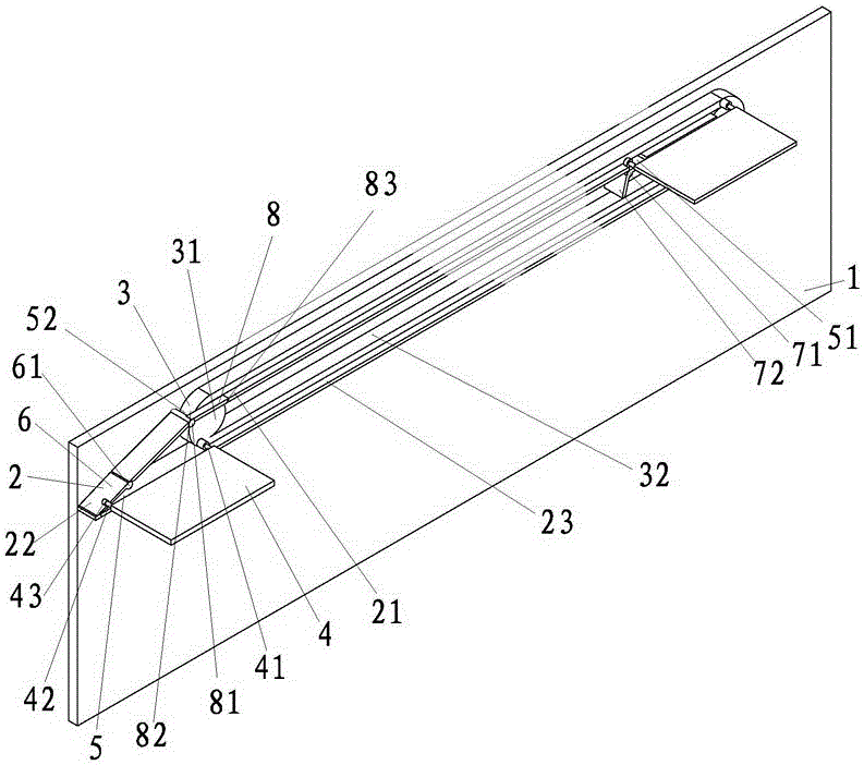
[0015] like figure 1 The transmission device of the CNC chain automatic printing machine shown includes a support frame 1, a guide mechanism 2 and a transmission mechanism 3. The support frame 1 is provided with a guide mechanism 2 and a transmission mechanism 3. The transmission mechanism 3 is provided with a number of evenly arranged printing supports. plate 4, one end of the printing support plate 4 is connected to the transmission mechanism 3, and the other end is arranged in the guide mechanism 2; when the transmission mechanism 3 drives the printing support plate 4 to move or stops, the guide mechanism 2 cooperates with the transmission mechanism 3 to drive the printing support plate 4 Always keep parallel to the horizontal plane.

[0016] The transmission mechanism 3 includes gears 31 arranged at both ends of the support frame 1 and a transmission cha...


PUM


Abstract

The transmission device of a digitally controlled chain-type automatic printing machine belongs to the technical field of printing equipment and includes a support frame, a guide mechanism and a transmission mechanism. The support frame is provided with a guide mechanism and a transmission mechanism, and the transmission mechanism is provided with a printing support plate. One end of the printing support plate is connected to the transmission mechanism, and the other end is arranged in the guide mechanism; when the transmission mechanism drives the printing support plate to move or stop, the guide mechanism cooperates with the transmission mechanism to move the Above-mentioned printing support plate keeps parallel with horizontal plane all the time. The invention provides a numerical control chain type automatic printing machine transmission device which can be provided with a large printing support plate and has a small overall structure.

Description

technical field [0001] The invention belongs to the technical field of printing equipment, and in particular relates to a transmission device of a digitally controlled chain automatic printing machine. Background technique [0002] The existing public document with the publication number CN202986301U and the publication date is 2013.6.12 discloses a printing machine transmission structure for conveying a paper material, which includes a surface material and a base material that are attached to each other. The surface material and the base material can be separated from each other to form a bifurcation part, and the surface material and the base material can be attached to each other to form a bonding bifurcation part. The surface material includes a printing surface and a material bonding surface, and the base material includes a The bottom surface of the substrate and a bonding surface of the substrate, and the surface material are used to transport to a printing seat. The...

Claims


Application Information

Patent Timeline
Patent Type & Authority Patents(China)
IPC IPC(8): B41F15/08B41F15/14
Inventor 王林虎
Owner ZHEJIANG DONGHE PRINTING PACKAGING CO LTD
Learn More