
Cascaded multi-level-based ground overvoltage phase splitting device

A cascading multi-level, over-current phase-splitting technology, which is applied to power lines, transportation and packaging, and vehicle components, can solve the problems of increasing system complexity and cost, production cut-off overvoltage, and high switch requirements, and achieves Feed-through power supply, reducing requirements, avoiding cut-off overvoltage and closing surge overcurrent effects

Inactive Publication Date: 2014-05-28
SOUTHWEST JIAOTONG UNIV
View PDF5 Cites 28 Cited by
  • Summary
  • Abstract
  • Description
  • Claims
  • Application Information

AI Technical Summary

Problems solved by technology

It can be seen that the improved solution still cannot completely solve the shortcomings of the traditional ground over-current phase-splitting device, and the complexity and cost of the system are increased due to the need to use step-down transformers
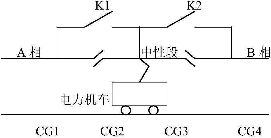
[0006] To sum up, there are the following problems in the existing ground over-current phase-splitting device: 1) Since it is a full-load breaking switch in the whole process, the requirements for the switch are relatively high; 2) When the neutral section voltage is converted, the load If the split-phase switch is disconnected, a cut-off overvoltage will be generated; 3) When the voltage is switched in the neutral section, the voltage phase before and after the switch is inconsistent, and there will be a difference in the steady-state magnetic flux of the traction transformer on the locomotive. Saturation causes closing surge overcurrent
For locomotives that rotate the motor and draw power from the traction transformer, it will also cause overcurrent in the auxiliary system when the switch is closed

Method used


Image

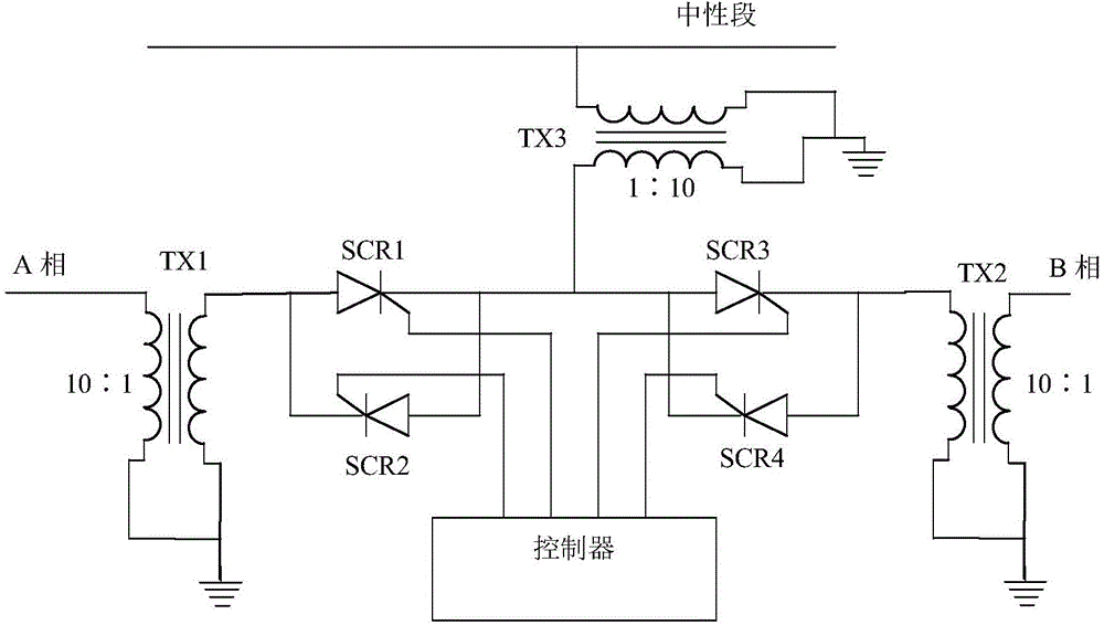
  • Cascaded multi-level-based ground overvoltage phase splitting device
  • Cascaded multi-level-based ground overvoltage phase splitting device
  • Cascaded multi-level-based ground overvoltage phase splitting device

Examples


Embodiment Construction

[0018] The present invention will be further described below in conjunction with drawings and embodiments.

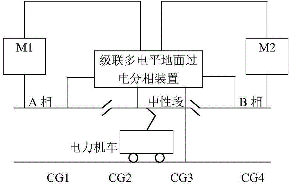
[0019] According to the determination of locomotive position by locomotive position sensors CG1, CG2, CG3 and CG4 on the track and the determination of catenary A and B phase voltage phases by catenary voltage phase detection modules M1 and M2 for measuring the catenary voltage phase , the output voltage is controlled by the controller of the cascaded multi-level ground over-current phase-splitting device, so that the electric locomotive can pass through the phase-separation flexibly. image 3 It is a system structure diagram of the cascaded multi-level ground overcurrent phase-splitting device designed by the present invention.

[0020] According to the existing technology, the cascaded multi-level ground overvoltage phase-splitting device can adopt the following structure: 1) cascaded H-bridge rectifier + cascaded H-bridge inverter; 2) cascaded H-bridge rectifier + ca...


PUM


Abstract

The invention discloses a cascaded multi-level-based ground overvoltage phase splitting device. The cascaded multi-level-based ground overvoltage phase splitting device is characterized in that the position of a train is determined by the aid of locomotive position sensors CG1, CG2, CG3 and CG4 which are arranged on a rail, a ground overvoltage phase splitting device which is connected to two adjacent phases outputs single-phase alternating-current voltages under the control, and amplitude values, frequencies and phases of the voltages are identical to an amplitude value, a frequency and a phase of a voltage of an A-phase bridge arm when the train is positioned on an A-phase bridge arm side; when an electric locomotive enters a neutral section, output voltage which is identical to the A-phase voltages the amplitude values, the frequencies and the phases of the A-phase voltages is converted to be identical to the B-phase amplitude values, frequencies and phases of the B-phase voltages. The cascaded multi-level-based ground overvoltage phase splitting device has the advantages that flexible passing voltage phase splitting can be implemented on the electric locomotive (or a motor train unit) by the aid of the cascaded multi-level-based ground overvoltage phase splitting device, impact on an overhead line system and the electric locomotive (or the motor train unit) can be prevented, and requirements on switch devices can be lowered; uninterrupted power supply passing voltage phase splitting can be implemented on the train; the cascaded multi-level-based ground overvoltage phase splitting device has an important significance on implementing through type power supply on the overhead line system with electric phase splitting.

Description

technical field [0001] The invention relates to the field of manufacturing AC / DC / AC electric locomotives (EMUs) and ground overcurrent phase separation devices for AC / DC electric locomotives. Background technique [0002] There are many methods for electric locomotive (EMU) over-voltage phase separation. In the early days, the speed of trains was relatively slow, and manual over-power phase separation was usually used. There was a phase-separation sign in the phase-separation area to instruct the driver to operate over-power phase separation. Before reaching the neutral section, the driver first reduces the traction level to 0, disconnects the auxiliary system, and then disconnects the main circuit breaker on the primary side of the traction transformer, so that the locomotive passes through the neutral section without electricity. After the locomotive enters the power supply area of ​​the power supply arm of the next phase, the driver closes the main breaker, starts the aux...

Claims


Application Information

Patent Timeline
IPC IPC(8): B60M3/04
Inventor 熊成林韩坤冯晓云王顺亮宋文胜
Owner SOUTHWEST JIAOTONG UNIV
Learn More