Screw conveyor

A technology of screw conveyor and conveying cylinder, applied in the field of conveying machinery, can solve the problems of broken bearing box sealing ring, poor coaxiality between the screw body and conveying cylinder wall, etc., so as to reduce maintenance times, improve production efficiency and avoid wear and tear. Effect

Inactive Publication Date: 2014-05-28
SHANGHAI SUQIAO MECHANICAL EQUIP
View PDF0 Cites 9 Cited by
  • Summary
  • Abstract
  • Description
  • Claims
  • Application Information

AI Technical Summary

Problems solved by technology

[0003] The technical problem to be solved by the present invention is: in order to overcome the problems of poor coaxiality between the existing conveyor screw body and the conveying cylinder wall, and the sealing ring of the bearing box is easily damaged by dust erosion, etc. Excellent screw conveyor with reasonable structure design

Method used


Image

  • Screw conveyor

Examples


Embodiment Construction

[0008] Now, the present invention will be described in further detail in conjunction with the accompanying drawings. These drawings are all simplified schematic diagrams, which only illustrate the basic structure of the present invention in a schematic manner, so they only show the configurations related to the present invention. After reading the content of the present invention, those skilled in the art can make various modifications to the present invention, and these equivalent changes and modifications also fall within the scope of protection defined by the present invention.

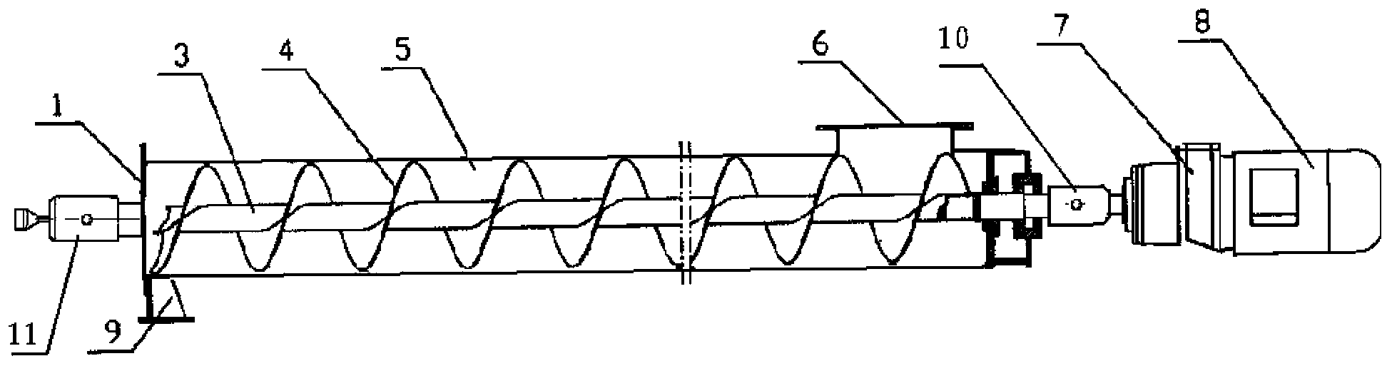
[0009] Such as figure 1 As shown, a screw conveyor includes a frame 9, a motor 8, a reducer 7, a delivery cylinder 5, a screw shaft 3, a screw body 4, a head drive bearing box 10 and a tail drive bearing box 11, and the frame 9 supports the delivery cylinder 5. There is a feed port 6 on the conveying cylinder 5, and the motor 8 drives the reducer 7 to drive the screw shaft 3 in the conveying pipe ...


PUM


Abstract

The invention discloses a screw conveyor which comprises a framework, a driving mechanism, a conveying drum, a screw shaft, a screw, a head transmission bearing box and a tail transmission bearing box. The conveying drum is supported by the framework, a material access port is formed in the conveying drum, the driving mechanism drives the screw in the conveying drum, a flange support is arranged at an end of the conveying drum, the screw shaft of the screw is supported by the flange support, and the head transmission bearing box and the tail transmission bearing box are respectively positioned on the outer portions of two ends of the screw. The screw conveyor has the advantages that the screw shaft is supported by the flange support, so that the coaxiality of the screw shaft can be guaranteed, and the screw shaft can be prevented from being abraded by the wall of the conveying drum; the head transmission bearing box and the tail transmission bearing box are separated from a shell, so that bearings in the bearing boxes can keep away from materials such as dust and are positioned in lubricated environments for a long time, the service lives of the bearings can be prolonged, a motor cannot be burned out easily, the maintenance frequency can be reduced, and the production efficiency can be improved.

Description

technical field [0001] The invention relates to the technical field of conveying machinery, in particular to a screw conveyor. Background technique [0002] At present, commonly used screw conveyors include a frame, a driving mechanism, a conveying cylinder, a screw shaft, and a spiral body. The conveying cylinder supported by the frame has an inlet and outlet, and the driving mechanism drives the spiral body in the conveying cylinder. However, the coaxiality between the delivery cylinder and the screw shaft of this kind of conveyor is poor, the position deviation is large, and the rotation resistance of the screw shaft is large, which in turn causes the technical problem of wear and tear between the spiral body and the delivery cylinder wall. In addition, when conveying powdery materials such as cement and flour over long distances, the bearing box of the screw conveyor is buried in ash powder and other materials for a long time, especially when high-temperature materials a...

Claims


Application Information

Patent Timeline
Patent Type & Authority Applications(China)
IPC IPC(8): B65G33/14B65G33/32
Inventor 黄正华
Owner SHANGHAI SUQIAO MECHANICAL EQUIP
Why Eureka
Try Eureka