
A sand fracturing process

A sand fracturing and process technology, which is applied in the direction of production fluid, wellbore/well components, earthwork drilling and production, etc., can solve the problems of high oil and gas resistance, low flow rate, shortened effective fracture length of oil and gas well fractures, etc., and achieve support and conduction Good flow capacity, good oil and gas seepage capacity, and the effect of reducing production costs

Active Publication Date: 2016-05-11
CHINA PETROLEUM & CHEM CORP +1
View PDF5 Cites 0 Cited by
  • Summary
  • Abstract
  • Description
  • Claims
  • Application Information

AI Technical Summary

Problems solved by technology

Therefore, the two cannot take into account high performance at the same time, and the usual measures are to balance
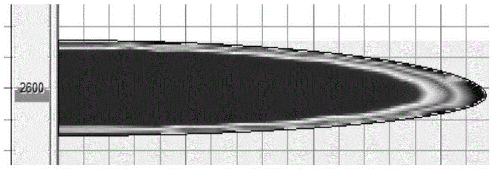
[0004] It is precisely because of the functional contradictions of the above-mentioned proppant that in the traditional sand fracturing process, the proppant that enters the fractures of the oil and gas well accumulates in the form of sand grains to form a sand column. After the gel is broken, no specific seepage channel can be formed in the sand column, and Seepage depends on the fine seepage channels formed by the sand column itself. The resistance of oil and gas is high and the flow rate is low, so the conductivity and oil and gas seepage capacity of the proppant sand column are very low.
In addition, with the passage of time, the sand-like proppant in the fractures of oil and gas wells accumulates (from the first section to the rear), which greatly shortens the effective fracture length of oil and gas well fractures, which seriously affects the single well production of oil and gas wells. This significantly increases the cost of oil and gas well production

Method used


Image

  • A sand fracturing process
  • A sand fracturing process
  • A sand fracturing process

Examples


Embodiment Construction

[0023] In the present invention, the fiber-containing sand-carrying fluid and the pure jelly spacer fluid are pumped into the cracks of oil and gas wells in an alternate cycle to form sand columns, that is, a section of fiber-containing sand-carrying fluid is first pumped into the cracks of oil and gas wells, and then the oil and gas A section of pure jelly spacer fluid is pumped into the fractures of the well, and then a section of fiber-containing sand-carrying fluid is pumped into the fractures of the oil and gas well...in this way, each section contains fiber-containing sand-carrying fluid and pure jelly Pumping volume of spacer fluid (i.e. volume, unit: m 3 ), should be comprehensively and reasonably determined by geological and engineering parameters such as the ratio of reservoir closure stress to Young’s modulus of oil and gas well reservoirs, the thickness of the pay zone, and the length of the perforation section, specifically through the following calculation model: ...


PUM


Abstract

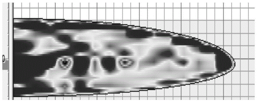
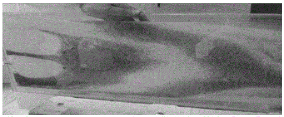
The invention discloses a sand fracturing technology. The technology is characterized in that fibrous sand-carrying fluid and pure gel interval fluid are pumped into oil-gas well cracks in a manner of alternate circulation; the fibrous sand-carrying fluid entering the oil-gas well cracks is dispersed into clusters different in shape by perforation shot holes in a tubular column; the cluster-shaped fibrous sand-carrying fluid is piled from inside to outside to form a sand column in the cracks; a gap between the adjacent fibrous sand-carrying fluid clusters in the sand column is filled by the pure gel interval fluid; the cross section of the whole sand column is in the shape of a piled stone wall; the cracks during a closing process and closed cracks are supported by the sand column; pure gel interval fluid parts in the sand column form a low-resistance and high-flow rate seepage passage of oil gas after gel breaking. According to the sand fracturing technology disclosed by the invention, under the flow conductivity of the excellent support of the oil-gas well cracks, the oil gas seeps at large area, low resistance and high flow rate, and further, the well yield of an oil-gas well is greatly increased, and the production cost of the oil-gas well is effectively reduced; the sand fracturing technology is strong in practicability and high in reliability.

Description

Technical field: [0001] The invention relates to a hydraulic fracturing stimulation technology for oil and gas well exploitation, in particular to a sand-added fracturing technology. Background technique: [0002] Fracturing stimulation is an important technology for production stimulation of low permeability oil and gas wells. The key to realizing the fracturing stimulation process is to support the fractures of oil and gas wells. Through the effective support of oil and gas well fractures, good fracture conductivity can be ensured, thereby increasing oil and gas production. However, the propping of oil and gas well fractures by traditional sand fracturing technology relies on continuous pumping of uniform proppant, which makes the conductivity of oil and gas well fractures completely depend on the conductivity of the proppant sand column itself. It is bound to require that the proppant itself needs to take into account two functions, one function is to support the functio...

Claims


Application Information

Patent Timeline
Patent Type & Authority Patents(China)
IPC IPC(8): E21B43/267
Inventor 甘振维戚斌任山刘林黄禹忠黄小军王兴文杨衍东王文耀刘斌宋燕高慈建发李永明邱玲腾小兰方行刘琦付育武
Owner CHINA PETROLEUM & CHEM CORP
Learn More