Dual clutch automatic transmission cooling flow control method and system

A technology of automatic transmission and double clutch, which is applied in the direction of gear lubrication/cooling, transmission parts, belt/chain/gear, etc., which can solve the problem of large degree of first clutch slipping and insufficient gear lubrication, which affects the use of clutches and gears Life and other issues, to increase driving safety, avoid the impact of shifting pressure, and prolong the service life

Active Publication Date: 2014-05-28
ANHUI JIANGHUAI AUTOMOBILE GRP CORP LTD
View PDF6 Cites 13 Cited by
  • Summary
  • Abstract
  • Description
  • Claims
  • Application Information

AI Technical Summary

Problems solved by technology

However, during the normal running of the vehicle, when the engine speed is stable at a certain speed, the total amount of oil output from the oil pump is constant, that is, the total amount of cooling oil flowing through the dual clutch and cooling oil flowing through the gears Yes, when the flow of cooling oil flowing through the dual clutch increases, the flow of cooling oil flowing through the gears will decrease relatively. If the flow distribution is carried out without considering the actual operating conditions of the vehicle , it is very likely that the amount of cooling oil distributed to the dual clutch is too small or the amount of cooling oil distributed to the gear is too small, resulting in a relatively low degree of slipping between the driving disc and the driven disc of the first clutch or the second clutch. large, or the lubrication of the gears is insufficient, which affects the service life of the clutch and gears and reduces the safety of driving the vehicle

Method used


Image

  • Dual clutch automatic transmission cooling flow control method and system
  • Dual clutch automatic transmission cooling flow control method and system
  • Dual clutch automatic transmission cooling flow control method and system

Examples


Embodiment Construction

[0065] Embodiments of the present invention are described in detail below, examples of which are shown in the drawings, wherein the same or similar reference numerals designate the same or similar elements or elements having the same or similar functions throughout. The embodiments described below by referring to the figures are exemplary only for explaining the present invention and should not be construed as limiting the present invention.

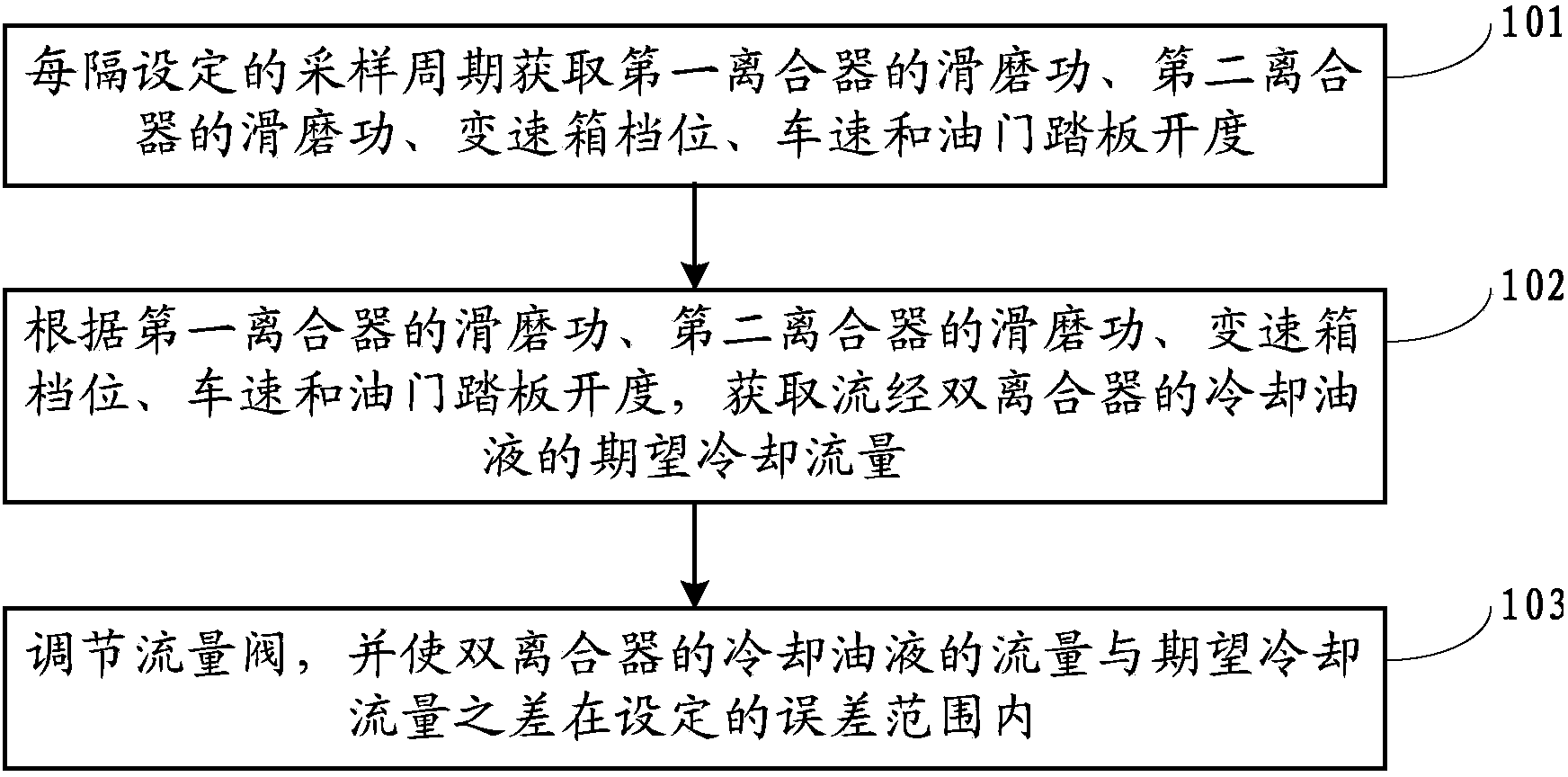
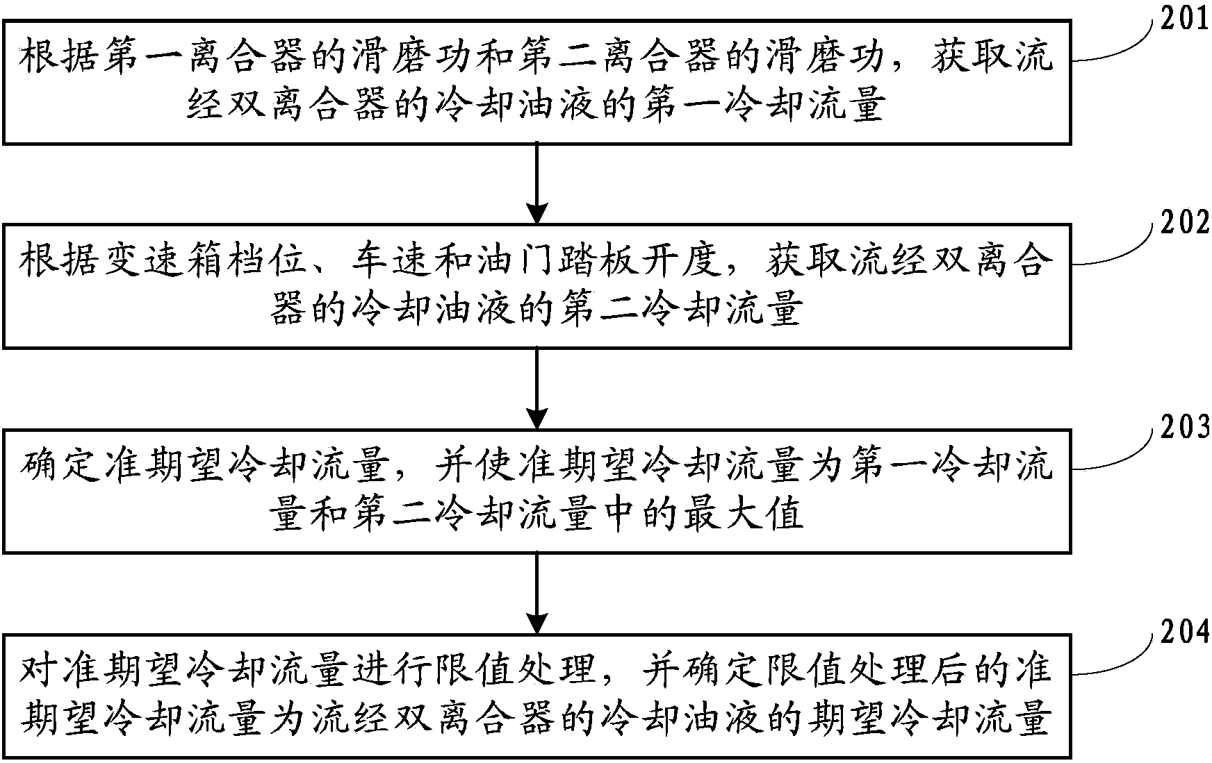
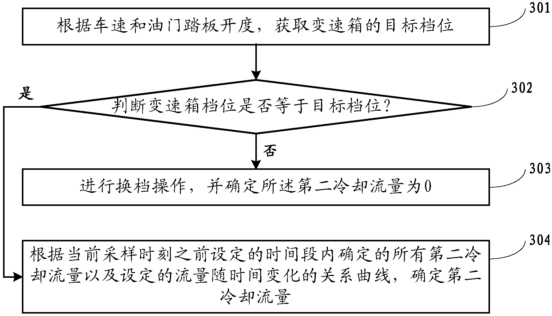
[0066] The cooling flow control method of the dual-clutch automatic transmission in the embodiment of the present invention uses three aspects of the clutch sliding work, the dual-clutch oil temperature and the transmission oil temperature, and the shifting state to jointly determine the desired dual-clutch cooling flow, taking into account the overall system The balanced relationship between cooling flow control and lubrication is conducive to providing an appropriate amount of cooling flow for the dual clutch according to the actual sit...


PUM


Abstract

The invention discloses a dual clutch automatic transmission cooling flow control method and a system. The dual clutch automatic transmission cooling flow control method comprises the following steps that work of slipping of a first clutch, work of slipping of a second clutch, a transmission gear, a speed and a accelerator pedal opening are obtained at every set sampling period; expected cooling flow of cooling oil flowing through the dual clutch is obtained based on work of slipping of the first clutch, work of slipping of the second clutch, the transmission gear, the speed and the accelerator pedal opening; flow valve is adjusted and differential flow between the flow of cooling oil of the dual clutch and the expected cooling flow is made in the set error range. According to the dual clutch automatic transmission cooling flow control method and the system, expected dual clutch cooling flow is codetermined by adopting work of slipping of the clutch, oil temperature of the dual clutch, oil temperature of the transmission and a shifting state, balanced relation between the cooling flow control and lubrication of the system is fully considered, so that moderate cooling flow can be appropriately provided to the dual clutch based on actual condition and adverse effects caused by excessive cooling and insufficient lubrication can be avoided.

Description

technical field [0001] The invention relates to the technical field of automatic transmissions for automobiles, in particular to a cooling flow control method and system for a dual-clutch automatic transmission. Background technique [0002] A typical wet dual clutch automatic transmission is mainly composed of an oil pump, a wet dual clutch, an electronic control system, a hydraulic system, gears and other hardware. A wet dual clutch automatic transmission includes a first clutch (also known as an outer clutch), a second clutch (also known as an inner clutch), an outer input shaft, and an inner input shaft, where the outer input shaft connected to the first clutch controls the odd gears The gear, the inner input shaft connected with the second clutch controls the even-numbered gear and the reverse gear, and the combination and separation of each gear are controlled by the electronic control system and the hydraulic system. When changing gears, one clutch de-energizes an en...

Claims


Application Information

Patent Timeline
Patent Type & Authority Applications(China)
IPC IPC(8): F16H57/04
CPCF16H57/0434
Inventor 王烨
Owner ANHUI JIANGHUAI AUTOMOBILE GRP CORP LTD
Why Eureka
Try Eureka