Method, device and system for processing handle signals

A handle and signal technology, applied in the field of control, can solve problems such as poor system stability and inability to meet operation control, and achieve the effect of improving fretting and stability

Active Publication Date: 2014-05-28
ZOOMLION HEAVY IND CO LTD
View PDF6 Cites 8 Cited by
  • Summary
  • Abstract
  • Description
  • Claims
  • Application Information

AI Technical Summary

Problems solved by technology

[0007] Aiming at the problem in the related art that after buffering the controller, the result of the buffering process is fixed, resulting in the problem of being unable to meet more precise operation control and poor system stability, no effective solution has been proposed so far. Therefore, the present invention The main purpose is to provide a handle signal processing method, device and system to solve the above problems

Method used


Image

  • Method, device and system for processing handle signals
  • Method, device and system for processing handle signals
  • Method, device and system for processing handle signals

Examples


Embodiment 1

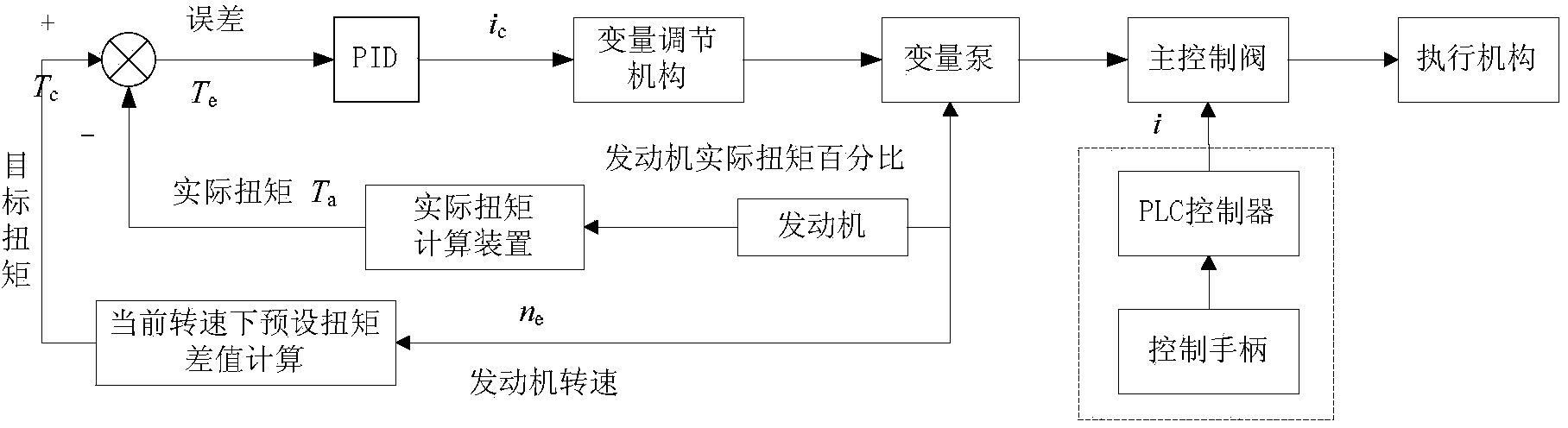
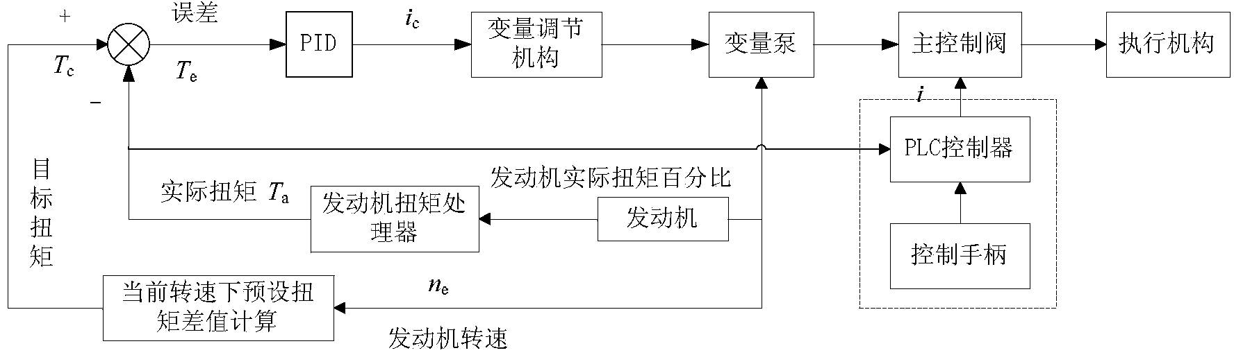
[0040] image 3 is a schematic structural diagram of a handle signal processing system according to an embodiment of the present invention. Such as image 3 As shown, the system includes: an engine; an engine torque processor, electrically connected to the engine, for generating and outputting the actual torque of the engine, in this embodiment, the engine torque processor can be an actual torque calculation device; a control handle, It is used to issue handle control instructions, and obtain the handle angle analog input value of the control handle according to the handle control instructions; the controller (such as a programmable logic controller (Programmable Logic Controller, referred to as PLC)), is set in the engine torque processor and Between the control handles, it is used to receive the actual torque of the engine and the handle angle analog input value of the control handle, and then determine the preset step length setting value of the controller according to the...

Embodiment 2

[0058] Figure 6 is a flowchart of a handle signal processing method according to an embodiment of the present invention, Figure 7 is another flow chart of the handle signal processing method according to the embodiment of the present invention.

[0059] Such as Figure 6 The method shown includes the following steps:

[0060] Step S10, receiving the actual torque of the engine and the handle angle analog input value of the control handle.

[0061] Step S20, determining a preset step length setting value of the controller according to the received actual torque.

[0062] Step S30, detecting the change value of the handle angle analog input value in each control cycle.

[0063] In step S40, the analog output value of the handle is determined by comparing the change value of the input value of the handle angle analog value with the set value of the step length.

[0064] In this embodiment, after the controller receives the handle angle analog input value of the control han...

Embodiment 3

[0094] Figure 8 is a schematic structural diagram of a handle signal processing device according to an embodiment of the present invention. Figure 9 is another structural schematic diagram of a handle signal processing device according to an embodiment of the present invention. Such as Figure 8 As shown, the device includes: a receiving module 10, which is used to receive the actual torque of the engine and the handle angle analog input value of the control handle; a determination module 30, which is used to determine the step size setting of the controller according to the received actual torque value; the detection module 50 is used to detect the change value of the handle angle analog input value in each control cycle; the processing module 70 is used to compare the change value of the handle angle analog input value with the step size setting value to Determines the handle analog output.

[0095] Through the combined effect of the above modules: after the receiving m...


PUM


Abstract

The invention discloses a method, device and system for processing handle signals. The method includes the steps of receiving the actual torque of an engine and a handle angle analog quantity input value of a control handle, determining a step size set value preset by a controller according to the received actual torque, detecting change values of the handle angle analog quantity input value in each control period, and determining a handle analog output quantity by comparing the change values of the handle angle analog quantity input value and the step size set value. By means of the technical scheme, the problems that after the controller is buffered and processed in correlative techniques, due to the fact that a buffer processing result is fixed, the requirement for more precise operation control can not be met, and the problem that system stability is poor can be solved.

Description

technical field [0001] The present invention relates to the field of control, in particular to a method, device and system for processing handle signals. Background technique [0002] The limit power matching control technology is a control method commonly used by construction machinery to prevent the engine from stalling. According to the load change, according to a certain control algorithm, the system flow is adjusted by changing the swing angle of the variable pump swash plate, so as to achieve variable The purpose of automatic adjustment of the output power of the pump is to realize that the engine will not be overloaded under heavy load, will not turn off, and will not need too much power reserve to ensure safe and reliable operation of the equipment at full load. [0003] In practical application, because the adjustment of the variable pump and the engine power adjustment require a certain amount of adjustment time, and the gain of the control algorithm cannot be set ...

Claims


Application Information

Patent Timeline
IPC IPC(8): G05B19/05
Inventor 李迎兵刘伟李英智
Owner ZOOMLION HEAVY IND CO LTD
Why Eureka
Try Eureka