A kind of micro-channel heat dissipation method

A heat dissipation method and micro-channel technology, applied in indirect heat exchangers, lighting and heating equipment, electrical components, etc., can solve the problems of low heat dissipation efficiency, single heat source, fixed heat dissipation of the radiator, and achieve adjustable heat dissipation. Effect

Inactive Publication Date: 2017-01-04
UNIV OF ELECTRONICS SCI & TECH OF CHINA
View PDF11 Cites 0 Cited by
  • Summary
  • Abstract
  • Description
  • Claims
  • Application Information

AI Technical Summary

Problems solved by technology

[0007] The purpose of the present invention is to design a microchannel heat dissipation method for the deficiencies of the prior art, to overcome the defects of fixed heat dissipation, low heat dissipation efficiency, and only applicable to a single heat source in the current radiator, so as to achieve stable and efficient heat dissipation for multiple heat sources. tuned cooling purpose

Method used


Image

  • A kind of micro-channel heat dissipation method
  • A kind of micro-channel heat dissipation method
  • A kind of micro-channel heat dissipation method

Examples


example 1

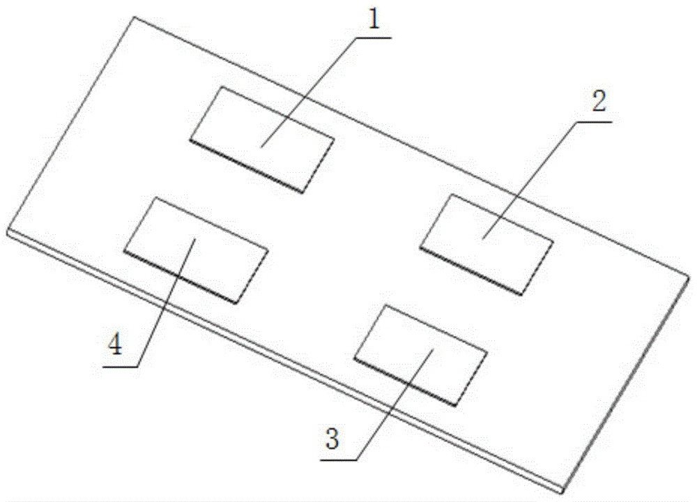
[0023] figure 2 and image 3 , is a preferred embodiment of the heat dissipation device of the present invention. Take this device working on a multi-chip circuit board as an example. The multi-chip board has 4 heat sources such as figure 1 As shown, the power of heat source 1 is 100W, the power of heat source 2 is 90W, the power of heat source 3 is 80W, the power of heat source 4 is 70W, and the area of ​​the four heat sources is 35mm×35mm, all of which are surface heat sources. The heat dissipation system includes a base, which is made of integral precision casting of aluminum, with a size of 140mm×140mm and a thickness of 2mm. A voltage-type temperature sensor is embedded in the base, the temperature detection range is 0-150°C, and it is connected with an external control unit. Prepared by mechanical processing methods on the substrate such as figure 2 For the multiple groups of micro-channels shown, the processing depth of the channels is 1 mm, and the width is 1 mm...

example 2

[0028] When the working condition of the heat source device may change, such as Figure 4 shown in the flow path instead of image 3 The structure of the heat dissipation channel shown in the figure, that is, the structure of the microchannel remains unchanged, and the thermal control method uses sensors to collect temperature and feed it back to the controller. The controller sends different signals to each flow control valve to control the flow rate according to the temperature. like Figure 4 As shown in , the size and number of parallel flow channels are consistent, which can adapt to various heat dissipation conditions. At the same time, in order to adjust the heat dissipation efficiency of each heat dissipation area to be consistent with the corresponding heat source. In order to adjust the heat dissipation efficiency of each heat dissipation area, this equipment is equipped with an adjustable flow solenoid valve at the position marked 16, which can control the flow of...


PUM


Abstract

The microchannel heat dissipation method of the invention is mainly used in the field of heat dissipation integrated with multiple high-power chip packaging boards. A temperature sensor is installed on each heat source integrated on the substrate, and the sensor is connected to an external controller. The cooling plate of the flow channel is covered above the substrate integrated with multiple heat sources. The controller controls the switching of the turbo pump and the fan according to the data collected by the temperature sensor; if the power of the heat source is fixed, set the appropriate micro-flow according to the power of each heat source The number of channels, the main channel is set with a regulating valve controlled by the controller to adjust the liquid flow; if the power of the heat source changes, the evenly distributed flow channel is used, and the bifurcation between the heat dissipation main channel and the micro-channels of each heat source is set by the controller The controlled flow solenoid valve adjusts the flow distribution of different power devices according to the actual working conditions, so that it has a stable, efficient and adjustable heat dissipation effect on multiple heat sources.

Description

[0001] Technical field: [0002] The invention relates to a heat dissipation method of a micro-flow channel, which belongs to the field of heat transfer and is applied to the field of heat dissipation integrated with a plurality of high-power chip packaging boards. [0003] Background technique: [0004] In recent years, with the development of microelectronics technology and electronic packaging technology, especially the continuous improvement of integrated circuits and device integration, the operating speed and output power of various electronic components have been continuously improved. Since high-power electronic components generate more heat, and high-density packaging distributes this heat on a smaller surface, it poses a great threat to the reliability of electronic components, and effective heat dissipation for electronic components is required. [0005] At the present stage, the liquid cooling method is aimed at a single heat source, and the use of microchannel heat...

Claims


Application Information

Patent Timeline
Patent Type & Authority Patents(China)
IPC IPC(8): H01L23/473H01L23/367F28D15/04
Inventor 徐尚龙郭宗坤郭威
Owner UNIV OF ELECTRONICS SCI & TECH OF CHINA
Why Eureka
Try Eureka