a gluing mechanism

A gluing and dispensing machine technology, applied in the direction of coating, liquid coating device on the surface, etc., can solve the problems such as failure to achieve uniform gluing, improve production and operation efficiency, simple structure and realization of functions, Effect of saving energy consumption

Inactive Publication Date: 2016-08-24
AD TOYO LIGHTING GUANGZHOU
View PDF6 Cites 0 Cited by
  • Summary
  • Abstract
  • Description
  • Claims
  • Application Information

AI Technical Summary

Problems solved by technology

However, the gluing mechanism devices currently in use have failed to achieve a better uniform gluing effect

Method used


Image

  • a gluing mechanism
  • a gluing mechanism

Examples


Embodiment

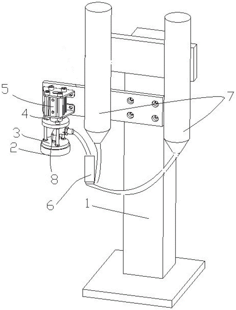
[0035] refer to figure 1 , is an embodiment of the gluing mechanism of the present invention.

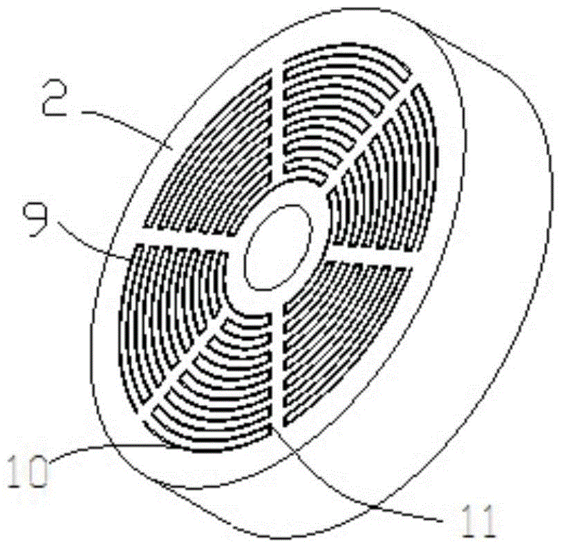
[0036] A gluing mechanism, including a glue dispensing machine, also includes: a bracket 1, a glue delivery cylinder 7, a one-way valve 6, a joint 8, a cylinder 5, a connecting bracket 4, a sleeve plate 3 and a gluing panel 2; wherein:

[0037] Bracket 1 is used for fixing and installing mechanism components.

[0038] The rubber tube 7 is used for storing the glue; the rubber tube 7 is installed on the bracket, the upper end of the rubber tube 7 is an input end, and the lower end is an output end.

[0039] The glue dispensing machine (not shown) is used to control the output volume of the glue liquid;

[0040] The one-way valve 6 is used to limit the flow direction of the glue solution and prevent the backflow of the glue solution;

[0041] The joint 8 is used for pipeline connection; the joint 8 is installed on the cover plate.

[0042] The cylinder 5 is used to drive the gluin...


PUM


Abstract

The invention provides a gluing mechanism, comprising a support, glue conveying cylinders, a non-return valve, a joint, an air cylinder, a connection support, a sleeve plate and a gluing panel, wherein the glue conveying cylinders are installed on the support, the upper end of each glue conveying cylinder is an input end, the lower end of each glue conveying cylinder is an output end, a dispensing machine is connected with the input ends of the glue conveying cylinders, the input end of the non-return valve is connected with the output ends of the glue conveying cylinders, the output end of the non-return valve is connected with the joint, the joint is mounted on the sleeve plate, the air cylinder is installed on the support, the connection support is connected with the air cylinder, the sleeve plate is mounted on the connection support, and the gluing panel is threadedly fixed with the sleeve plate. The gluing mechanism provided by the invention can realize uniform gluing; a glue solution does not flow back in the process of gluing, repeated conveying is avoided, energy is saved, and power consumption is reduced; through switching between the double glue conveying cylinders, there is sufficient time for filling of the glue conveying cylinders with the glue solution; the residual amount of the glue solution in the cylinders can be sensed. The gluing mechanism has a simple structure and good practicality.

Description

technical field [0001] The invention relates to the field of production and processing, in particular to a gluing mechanism. Background technique [0002] Many products are structurally inconvenient to use screws or rivets to connect and fix, and glue such as fixing glue is often used to fix the structure; therefore, whether the glue is applied uniformly and whether the coverage is wide enough can determine whether the structure is firm. In addition, in many electronic products, there are more or less components and components with high heat generation. When some components are overheated, they will not work properly, or even burn out, and further burn out adjacent components and components. Regardless of whether they are on the same board or not. Therefore, heat sinks are installed at the corresponding positions of components or components with high heat generation or even the entire circuit board to protect the stability of the product and prolong the service life, and th...

Claims


Application Information

Patent Timeline
Patent Type & Authority Patents(China)
IPC IPC(8): B05C5/02B05C11/10
Inventor 关崇安
Owner AD TOYO LIGHTING GUANGZHOU
Why Eureka
Try Eureka