Clamping mechanism

A technology of clamping mechanism and clamping parts, which is applied in the direction of collets, manipulators, metal processing, etc., can solve the problems of excessive deformation of clamping parts, limited driving force of pushing parts, and affecting clamping efficiency, etc. The effect of improving service life and clamping efficiency

Inactive Publication Date: 2014-06-04
HONG FU JIN PRECISION IND (SHENZHEN) CO LTD +1
View PDF8 Cites 14 Cited by
  • Summary
  • Abstract
  • Description
  • Claims
  • Application Information

AI Technical Summary

Problems solved by technology

However, in the process of repeated use, when the thrust of the pusher is uneven, multiple clamping pieces are prone to excessive deformation due to sudden changes in tension, resulting in damage to the clamping pieces, requiring frequent replacement of the clamping pieces, which affects the performance of the clamping mechanism. service life
In addition, due to the tolerance of the hole diameter, when using the same driving part, the driving force of the pushing part is limited, so that multiple clamping parts cannot be tightly opposed to the inner wall of the workpiece, resulting in multiple clamping parts not being able to clamp the workpiece tightly. thus affecting the clamping efficiency

Method used


Image

  • Clamping mechanism
  • Clamping mechanism
  • Clamping mechanism

Examples


Embodiment Construction

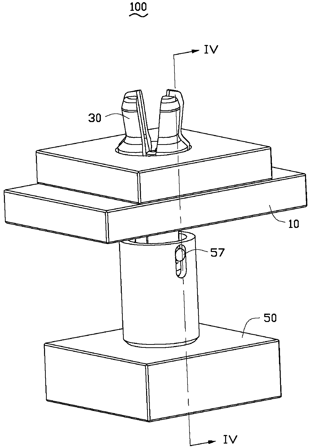
[0013] see figure 1 , the clamping mechanism 100 of the embodiment of the present invention is used to clamp a workpiece with a through hole (not shown in the figure). The clamping mechanism 100 includes a bearing base 10 , a clamping component 30 and a pushing component 50 . The bearing base 10 is connected with the mechanical arm (not shown in the figure), the clamping assembly 30 is passed through the bearing base 10 , the pushing assembly 50 is connected with the clamping assembly 30 , and can push the clamping assembly 30 to clamp the workpiece.

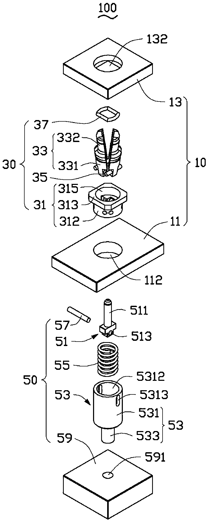
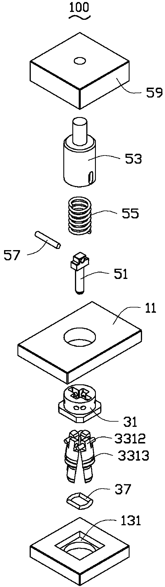
[0014] Please also refer to figure 2 , the bearing seat 10 includes a first mounting plate 11 and a second mounting plate 13 . The first mounting plate 11 is substantially in the shape of a rectangular plate, and a first through hole 112 is opened in the middle thereof. The second mounting plate 13 is mounted on one side of the first mounting plate 11 , and a fixing groove 131 is recessed on the side facing the first mountin...


PUM


Abstract

A clamping mechanism comprises a bearing base, a clamping assembly and a pushing assembly. The clamping assembly comprises at least two clamping parts, a fixed part and a limiting part, wherein the fixed part is fixedly arranged on the bearing base, a containing hole is formed in the fixed part in a through mode, the containing hole contains the clamping parts, part of each clamping part is exposed outside the fixed part, and the clamping parts are sleeved with the limiting part. The pushing assembly comprises a pushing part, an adjusting base and an elastic part, one end of the pushing part abuts against the clamping parts, one end, far away from the clamping parts, of the pushing part is movably arranged in the adjusting base, and the elastic part is arranged in the adjusting base and elastically abuts against the pushing part. The clamping mechanism has the advantages of being long in service life and high in clamping efficiency.

Description

technical field [0001] The invention relates to a clamping mechanism, in particular to a clamping mechanism for clamping workpieces with through holes. Background technique [0002] In the process of industrial processing, it is often necessary to clamp the workpiece to move and transport the workpiece. At present, the handling of the workpiece generally utilizes the cooperation of the mechanical arm and the clamping mechanism installed at the end of the mechanical arm to clamp and transport the workpiece. In order to prevent scratching the surface of the workpiece, the clamping mechanism clamps the workpiece through the hole on the workpiece. The existing clamping mechanism includes a driving part, a plurality of clamping parts and a pusher against the multiple clamping parts. When in use, multiple clamping parts are inserted into the holes of the workpiece, driven by the driving part, the pusher pushes the multiple clamping parts to spread outwards and resist against the...

Claims


Application Information

Patent Timeline
Patent Type & Authority Applications(China)
IPC IPC(8): B23Q7/04
CPCB25J15/0047B25J15/00B25J15/0226B25J15/10
Inventor 谢海方张朝乾彭应军郎文杰朱甫国
Owner HONG FU JIN PRECISION IND (SHENZHEN) CO LTD
Why Eureka
Try Eureka