Water gap shearing equipment

A technology of shearing equipment and nozzles, applied in the field of nozzle shearing equipment, can solve the problems of inconvenient setting, inconvenient replacement, and inability to cut and correct the processing volume of plastic parts, so as to avoid disordered distribution of mold cavities or counting errors, Improve the degree of automation and improve the effect of the overall image

Inactive Publication Date: 2014-06-04
深圳市壹零壹精密设备有限公司
View PDF8 Cites 28 Cited by
  • Summary
  • Abstract
  • Description
  • Claims
  • Application Information

AI Technical Summary

Problems solved by technology

[0002] Both the nozzle punching device and the nozzle shearing equipment have started to be used in the field of injection molding. Most of the existing nozzle punching devices are made according to the punching position of the plastic product, referring to the way of metal stamping. The cutting device is completely positioned, and the cut plastic parts have to be taken out manually, which is unsafe and the production efficiency is not high; the cutting of the nozzle is to cut the plastic parts by the upper and lower fixed knives, and the position of the knives has been fixed. Adjustment, the design of the knife group cannot perform shear correction on the offset of the plastic part, and cannot adapt to the shear position offset caused by the deformation of the plastic product, which often causes the shear position offset and the shear surface is not smooth; the position of the tool deviates The time adjustment is uncontrollable, and it is inconvenient to replace the tool when it is damaged. The actual production efficiency is not high, and the effect is very unsatisfactory. It is very inconvenient to adjust the positioning of the parts; generally, two-dimensional moving cutters are used for cutting processing. The cutting tool does not have the position correction when the plastic product is deviated. When the plastic part is deformed, the cutting position of the nozzle will deviate accordingly. The surface is uneven or the plastic product is damaged; when there are many nozzle positions that need to be cut, the two-dimensional movement method takes a long time to cut, and the efficiency is not high, and the automatic separation of the plastic parts is not convenient to realize, and the processing volume of the plastic parts is not large. Easy to set
[0003] In summary, the existing nozzle shearing equipment obviously has inconvenience and defects in actual use, so it is necessary to improve it

Method used


Image

  • Water gap shearing equipment
  • Water gap shearing equipment
  • Water gap shearing equipment

Examples


Embodiment Construction

[0035] In order to make the objectives, technical solutions and advantages of the present invention clearer, the following further describes the present invention in detail with reference to the accompanying drawings and embodiments. It should be understood that the specific embodiments described herein are only used to explain the present invention, but not to limit the present invention.

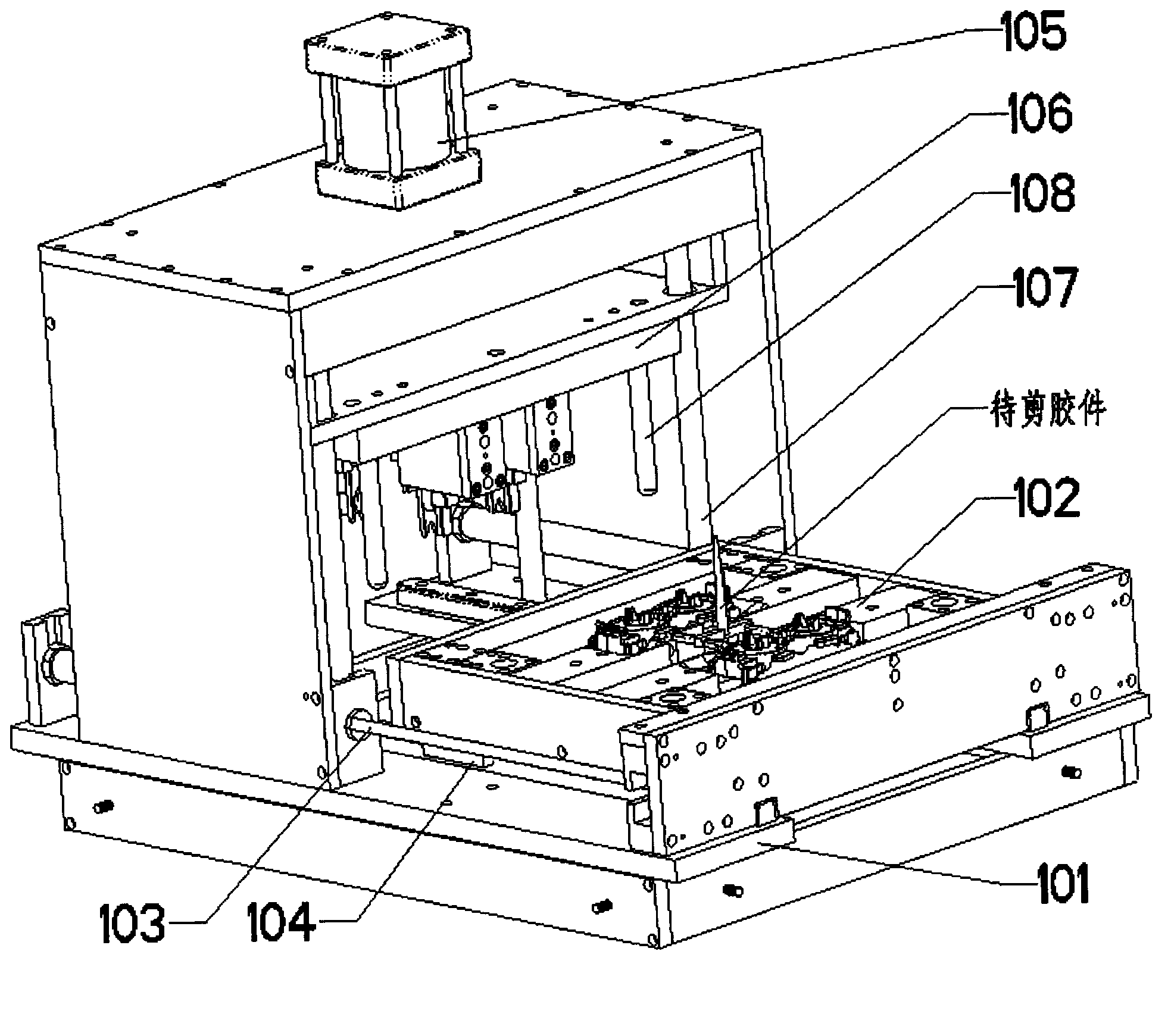
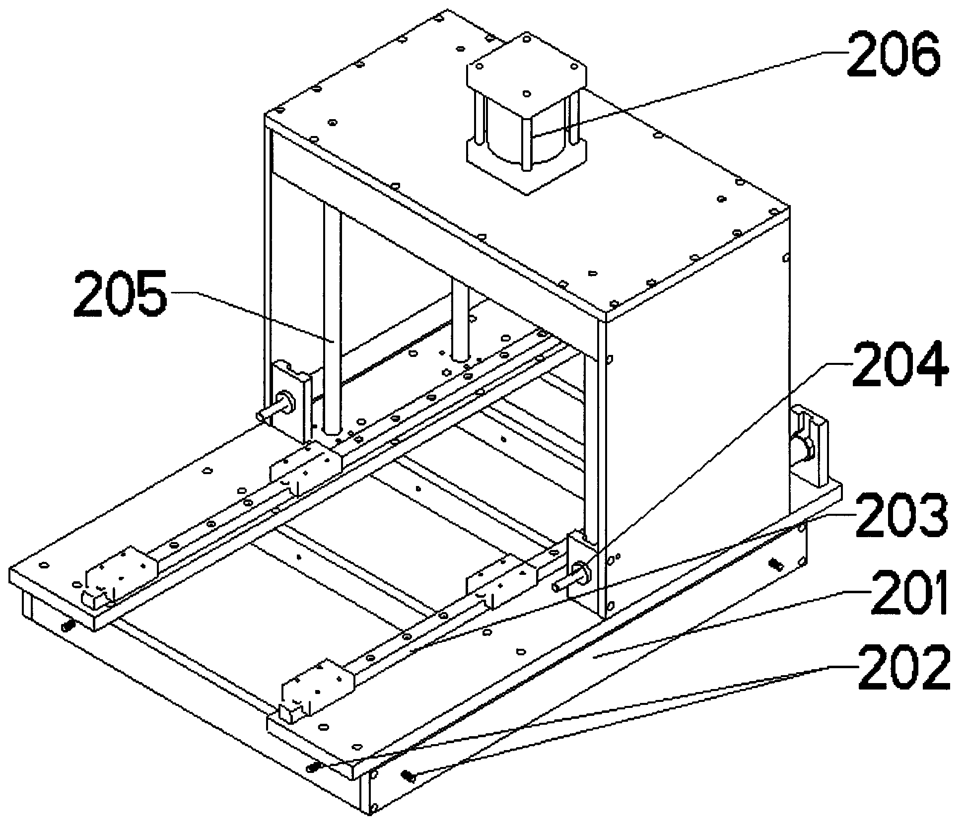
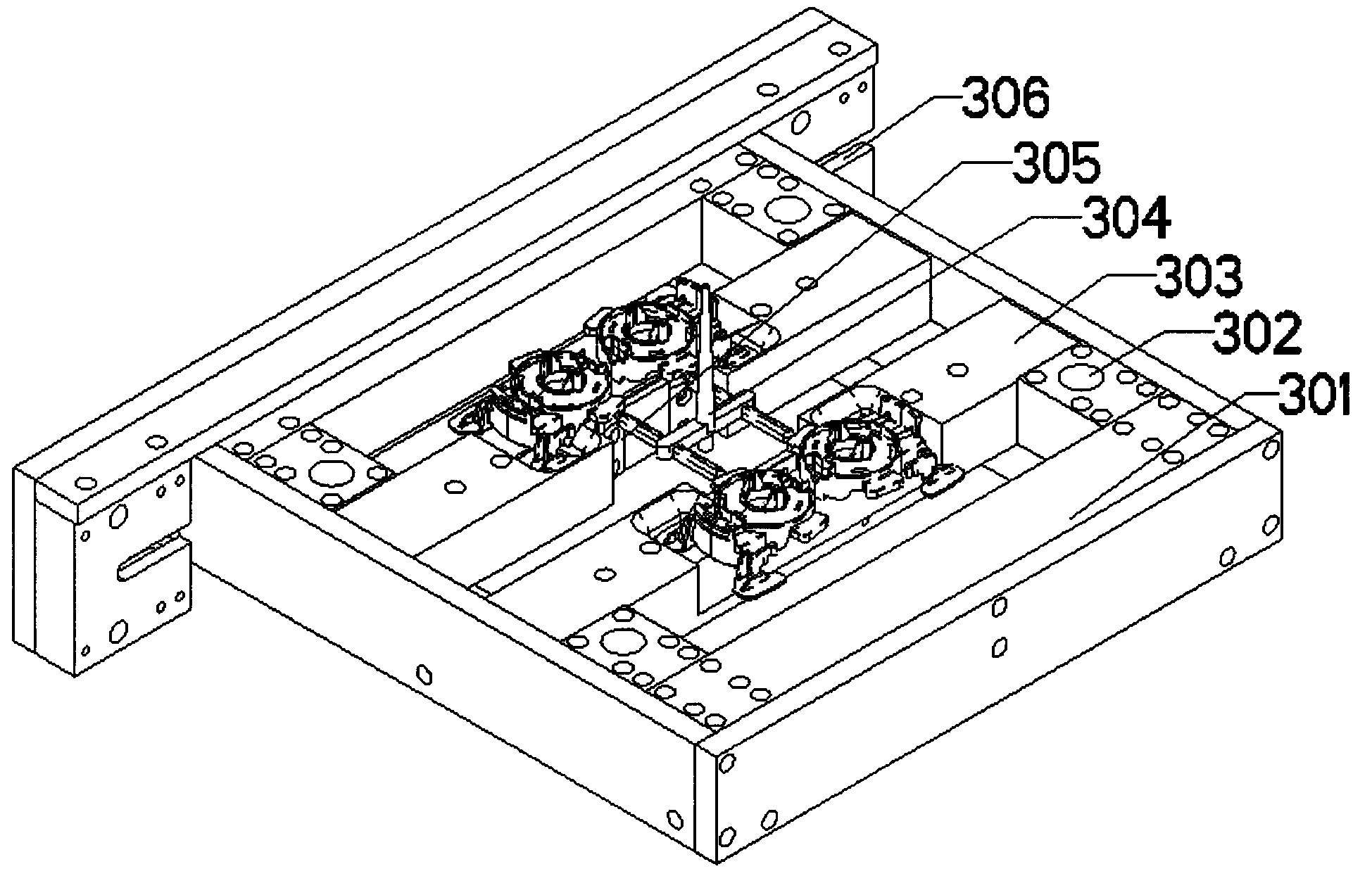
[0036] Such as figure 1 As shown, the present invention provides a nozzle cutting device with a main chassis, and the device also includes a main frame 101 ( figure 2 Show the overall structure), the main frame 101 above the lower platform is provided with a moving slider 104 and a horizontally propelling cylinder 103. A plastic product positioning device 102 is installed on the linear guide 104 ( image 3 Show the overall structure), the upper platform of the main frame 101 is equipped with a main cutting cylinder 105 and an upper tool holder 106 connected to the main cutting cylinder ( Figu...


PUM


Abstract

The invention provides water gap shearing equipment, comprising a main body machine case and a main body frame, wherein the main body frame comprises an upper platform and a lower platform; a linear lead rail and a horizontal propelling cylinder are arranged on the lower platform; a plastic product positioning device is arranged on the linear lead rail; the horizontal propelling cylinder is used for propelling the plastic product positioning device; a main cutting cylinder and an upper knife rest connected with the main cutting cylinder are arranged on the upper platform; at least two guide shafts for shearing and positioning and a guide post for guiding the upper knife rest to move up and down are arranged on the upper knife rest; the main body frame is provided with an adjusting screw for adjusting change of a front position between the main body machine case and the main body frame; at least one plastic product positioning die is arranged on the plastic product positioning device; a lower auxiliary shearing knife is arranged on the positioning die; at least one knife tackle positioning template is arranged below the upper knife rest; and an upper shearing knife tackle is arranged on the knife tackle positioning template. Thus, the cost can be reduced; and the shearing efficiency and quality are improved.

Description

Technical field [0001] The invention relates to the technical field of machinery, in particular to a nozzle shearing device. Background technique [0002] Nozzle punching devices and nozzle cutting devices have begun to be used in the injection molding field. Most of the existing nozzle punching devices are based on the punching position of the plastic product, referring to the metal stamping method. The plastic parts are used in the punching. The cutting device is completely positioned. The cut plastic parts must be removed manually, which is not safe and the production efficiency is not high; the nozzle is cut by the upper and lower fixed knives to cut the plastic parts, and the position of the knives has been fixed. Transfer, the design of the knife set cannot cut and correct the offset of the plastic part, and cannot adapt to the offset of the shearing position caused by the deformation of the plastic product. It often causes the offset of the shearing position and the sheari...

Claims


Application Information

Patent Timeline
Patent Type & Authority Applications(China)
IPC IPC(8): B29C45/38
CPCB29C45/382
Inventor 谢美兰
Owner 深圳市壹零壹精密设备有限公司
Why Eureka
Try Eureka