Rotatable engine mounting structure of overhead working vehicle

A technology for rotating engines and aerial work vehicles, applied in power units, vehicle parts, transportation and packaging, etc., can solve problems such as large vibration of engine mounts and platforms, difficult installation, damage to hydraulic pumps and engine accessories, etc. Maintenance performance, easy installation and maintenance, and the effect of solving large vibrations

Active Publication Date: 2014-06-04
CHTC JOVE HEAVY IND
View PDF5 Cites 5 Cited by
  • Summary
  • Abstract
  • Description
  • Claims
  • Application Information

AI Technical Summary

Problems solved by technology

[0006] (1) Difficult maintenance problems caused by the small gap between the engine of the aerial work vehicle and the vertical plate;
[0007] (2) The excessive rotation of the engine after the rotary installation damages the hydraulic pump and engine a

Method used


Image

  • Rotatable engine mounting structure of overhead working vehicle
  • Rotatable engine mounting structure of overhead working vehicle
  • Rotatable engine mounting structure of overhead working vehicle

Examples


Embodiment Construction

[0029] Embodiments of the present invention will be described in detail below in conjunction with the accompanying drawings, but they are not used to limit the scope of the present invention.

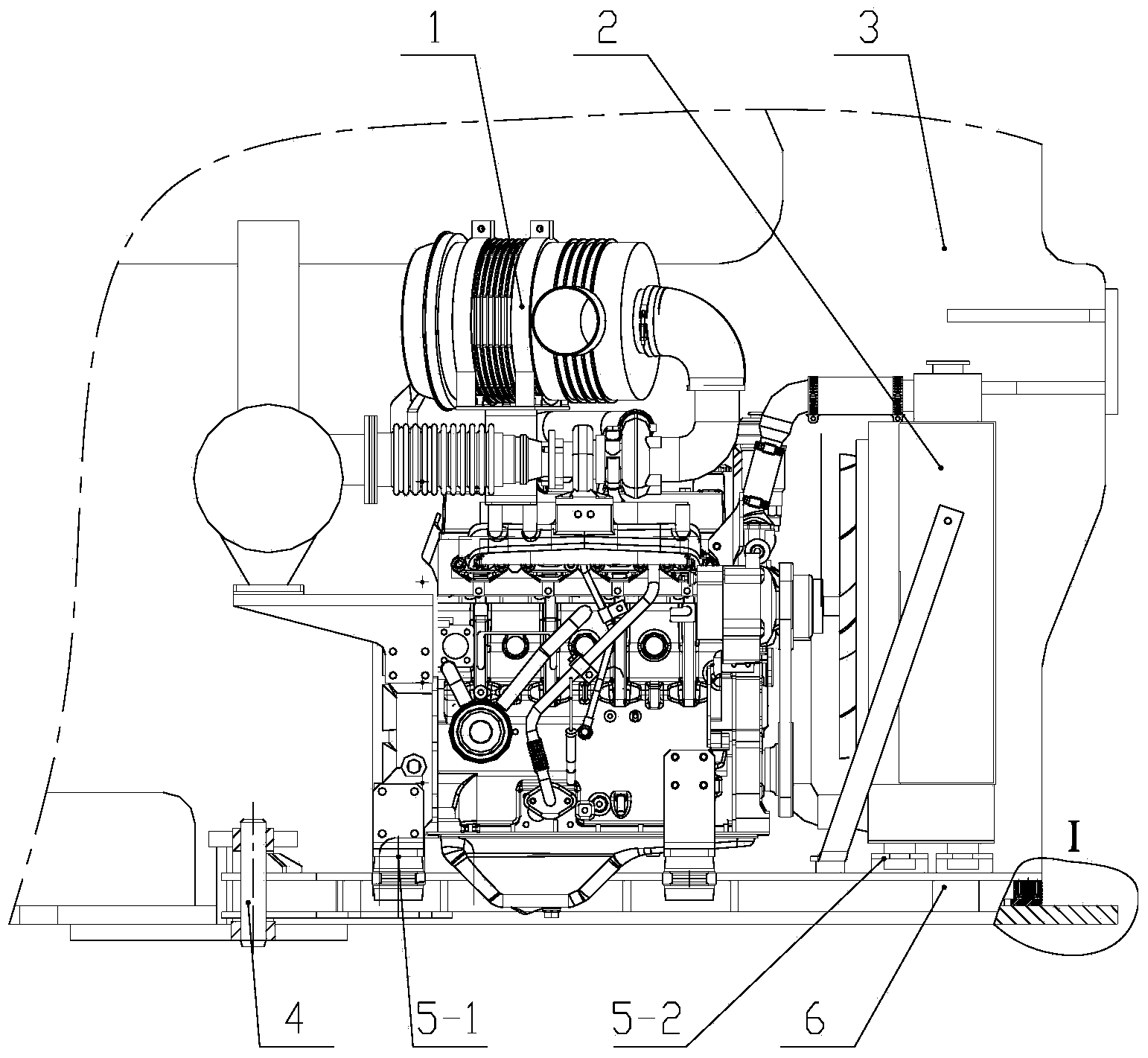
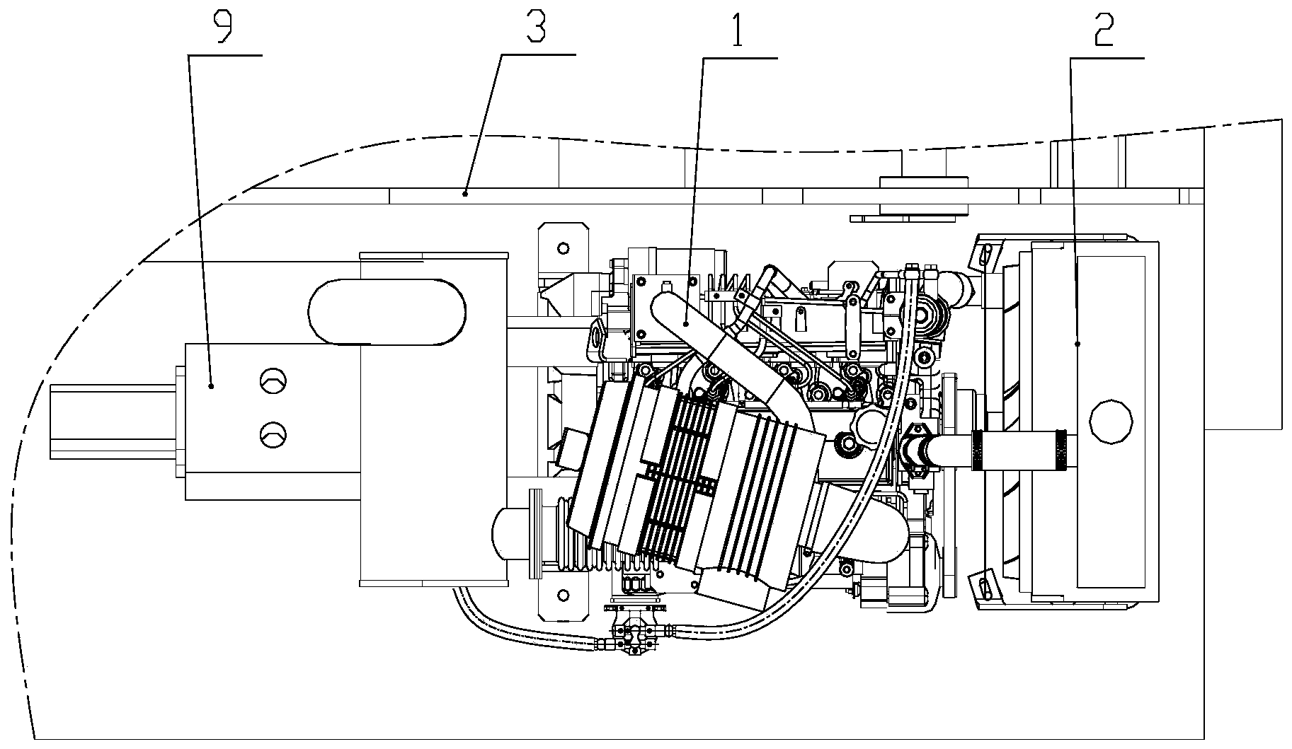
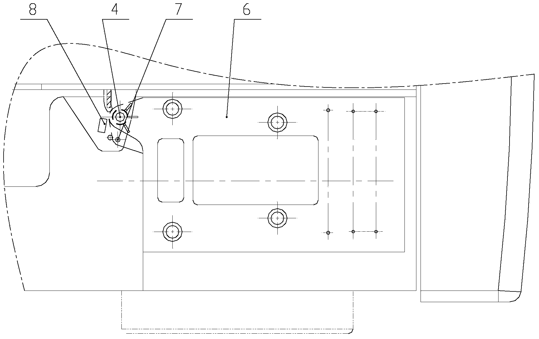
[0030] Such as Figure 1-3 As shown, the engine installation structure of this embodiment includes a fuel engine 1 for aerial work vehicles, a radiator 2, and a hydraulic pump 9 installed on the fuel engine 1 through a coupling. 5-1, 5-2 are connected to the engine mounting base 6, and the engine mounting base 6 is connected to the chassis lug of the platform 3 of the aerial work vehicle through the rotating pin 4, so that the engine mounting base 6 drives all the parts on it The whole can rotate a certain angle around the rotation axis 4. In order to reduce the difficulty of noise control, an oil-free bearing is provided between the rotating pin shaft 4 and the fixed frame, which replaces the rolling bearing commonly used in the prior art, and the processing and installation are also ...


PUM


Abstract

A rotatable engine mounting structure of an overhead working vehicle comprises an engine mounting base (6) rotatably connected with a get-on platform (3), the engine mounting base is a support body comprising a rectangular groove shape, an upper lug and a lower lug which are parallel to each other are arranged on the side face of the engine mounting base, a benchmark positioning hole is formed in a chassis of the get-on platform, the engine mounting base (6) is connected with the benchmark positioning hole in a pivot mode through a rotating pin shaft (4), and therefore the engine mounting base can rotate between the working position and the maintenance position. A rubber cushion block (11) is fixedly connected with the bottom of the engine mounting base (6). The structure further comprises a guide plate (15), the guide plate is fixedly connected with the chassis of the get-on platform (3), and the rubber cushion block (11) is supported on the guide plate. The mounting structure can achieve engine rotation in the narrow space, maintenance of the engine is facilitated, meanwhile, the problem of difficult screwing in and screwing out caused by large vibration between the engine and the platform and the machining error is solved, and the structure is simplified.

Description

technical field [0001] The invention relates to an installation structure, in particular to the technical field of an installation seat that can be used for a rotatable engine of an aerial work vehicle. Background technique [0002] Self-propelled aerial work vehicle is a special vehicle for transporting staff and equipment to the designated operating height for special operations. It is gradually replacing traditional scaffolding and is widely used in municipal construction, large-scale construction sites and construction facilities, maintenance of chemical equipment, Surface decoration projects such as ship repair, welding and painting work, such as for the 2010 Shanghai World Expo, built more than 100 venues of various types. The internal height and structural characteristics of these venues determine that aerial work vehicles are almost indispensable in their construction and use. [0003] The above-mentioned high-altitude operation vehicles generally use fuel power or ...

Claims


Application Information

Patent Timeline
IPC IPC(8): B60K5/12
Inventor 梁业轩黎起富李仕刘文彬黄敏
Owner CHTC JOVE HEAVY IND
Why Eureka
Try Eureka