Electrorheological buffer

A buffer, electrorheological technology, used in shock absorbers, shock absorbers, springs/shock absorbers, etc., can solve problems such as limited adjustment range, fixed stiffness and damping characteristics, and inability to adjust the buffer effect.

Inactive Publication Date: 2014-06-04
BEIJING INSTITUTE OF TECHNOLOGYGY
View PDF6 Cites 21 Cited by
  • Summary
  • Abstract
  • Description
  • Claims
  • Application Information

AI Technical Summary

Problems solved by technology

[0004] A common feature of the above-mentioned buffers is that the buffering effect cannot be properly adjusted according to the change of the i

Method used


Image

  • Electrorheological buffer
  • Electrorheological buffer
  • Electrorheological buffer

Examples


Embodiment Construction

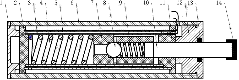
[0014] The present invention is an electrorheological buffer, which mainly includes: rear end cover 1, rear insulating sleeve 2, inner cylinder 3, metal spring 4, middle cylinder 5, outer cylinder 6, piston 7, one-way valve pin 8, one-way valve metal Spring 9, piston rod 10, front insulating sleeve 11, front end cover 12, star seal ring 13 and collision head rubber sleeve 14. by figure 1 For example, when the rubber sleeve 14 of the bumper bumper is subjected to an external impact load, the piston rod 10 of the buffer moves to the left, pushing the piston 7 to compress the metal spring 4, and making the electrorheological fluid in the rodless cavity flow from the left end of the inner cylinder 3 part of the electrorheological fluid flows to the rod chamber through the annular electric field formed by the inner cylinder 3 and the middle cylinder 5, and part of it flows through the fluid hole at the lower left end of the middle cylinder 5 to the annular oil storage formed by the...


PUM


Abstract

An electrorheological buffer has a damping continuously adjustable function, is used for various communication and transportation facilities and engineering machines and achieves semi-active control over impact loads borne by the electrorheological buffer. The buffer mainly comprises a buffer piston, a piston rod, an inner cylinder barrel, a middle cylinder barrel, an outer cylinder barrel, a one-way valve, a front insulating bush, a rear insulating bush, a seal ring and the like, wherein the one-way valve, the front insulating bush, the rear insulating bush and the seal ring are used in the buffer recovery process. The inner cylinder barrel and the middle cylinder barrel of the buffer are used as electrodes, and an annular space formed by the inner cylinder barrel and the middle cylinder barrel of the buffer serves as a high-voltage direct-current electric field. By means of continuous control of an external electric field, damping force of the buffer can be continuously controlled and adjusted; an annular space formed by the middle cylinder barrel and the outer cylinder barrel is a liquid storage chamber and is used for storing and supplementing liquid needed by a working chamber when the piston rod enters and leaves the buffer; the three cylinder barrels of the buffer are separated and positioned at certain gaps through the front insulating bush and the rear insulating bush; the one-way valve is arranged on the buffer piston and fixed through the piston rod, and the one-way valve is closed in the buffer recovery process and opened in the compression process.

Description

technical field [0001] The invention is a novel damping continuously adjustable buffer, which is used in various transportation equipment and engineering machinery to realize semi-active control of various impact loads it receives. Background technique [0002] All kinds of buffers are widely used in transportation equipment, such as vehicles, aircraft, and ships. By prolonging the action time of impact loads, absorbing and converting the energy of impact loads, the purpose of slowing down the rigid collision of equipment can be achieved. [0003] At present, the common buffers are generally rubber buffers, metal spring buffers, hydraulic (pneumatic) buffers and their combined buffers. The rubber buffer has simple structure, low manufacturing cost, good elasticity and sufficient strength, and is widely used in many industrial equipment and daily life. However, rubber buffers have limited elastic deformation and limited kinetic energy absorption, and are most suitable for ap...

Claims


Application Information

Patent Timeline
IPC IPC(8): F16F9/32
Inventor 张少华林程王文伟
Owner BEIJING INSTITUTE OF TECHNOLOGYGY
Why Eureka
Try Eureka