High/low speed bidirectional damping adjustable mechanical damper

A two-way damping and shock absorber technology, which is applied to shock absorbers, liquid shock absorbers, shock absorbers, etc. Convenient damping characteristics, small changes in external dimensions, and easy-to-achieve effects

Inactive Publication Date: 2013-11-06
JILIN UNIV
View PDF1 Cites 0 Cited by
  • Summary
  • Abstract
  • Description
  • Claims
  • Application Information

AI Technical Summary

Problems solved by technology

However, it is difficult for existing adjustable damping mechanical shock absorbers to independently adjust the damping coefficient of the shock absorber at low and high speeds in the tension and compression strokes.
[0005] After searching patent documents, for example, Chinese patent announcement number CN201068948Y, announcement date 2008.06.04, application number 200720094130.1, application date 2007.05.26, the applicant Jilin University, the name is "damping adjustable shock absorber", the technical solution of the application Although the damping adjustable shock absorber described above can adjust the damping force of the shock absorber through the bypass valve of the shock absorber, since there is only one set of adjustment devices, the low-speed and high-speed working conditions of the shock absorber cannot be adjusted separately. Moreover, the adjustment process affects both the tensile stroke damping force and the compression stroke damping force of the shock absorber, which cannot be individually and flexibly adjusted, and it is difficult to accurately obtain the ideal damping characteristics of the shock absorber

Method used


Image

  • High/low speed bidirectional damping adjustable mechanical damper
  • High/low speed bidirectional damping adjustable mechanical damper
  • High/low speed bidirectional damping adjustable mechanical damper

Examples


Embodiment Construction

[0038] The present invention is described in detail below in conjunction with accompanying drawing:

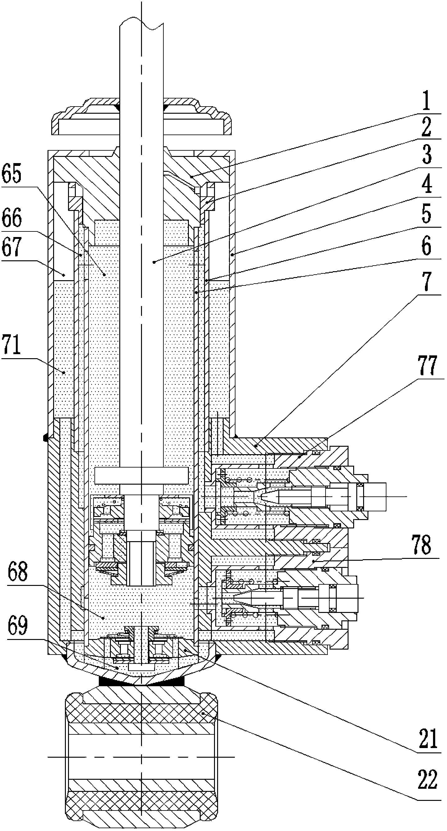
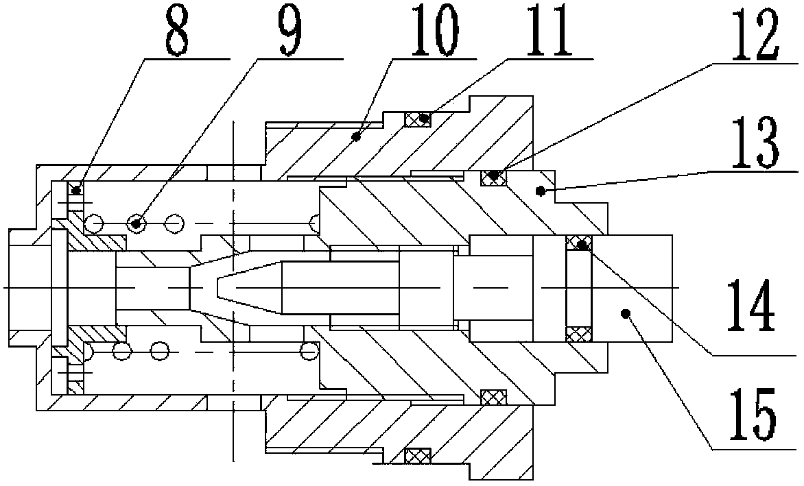
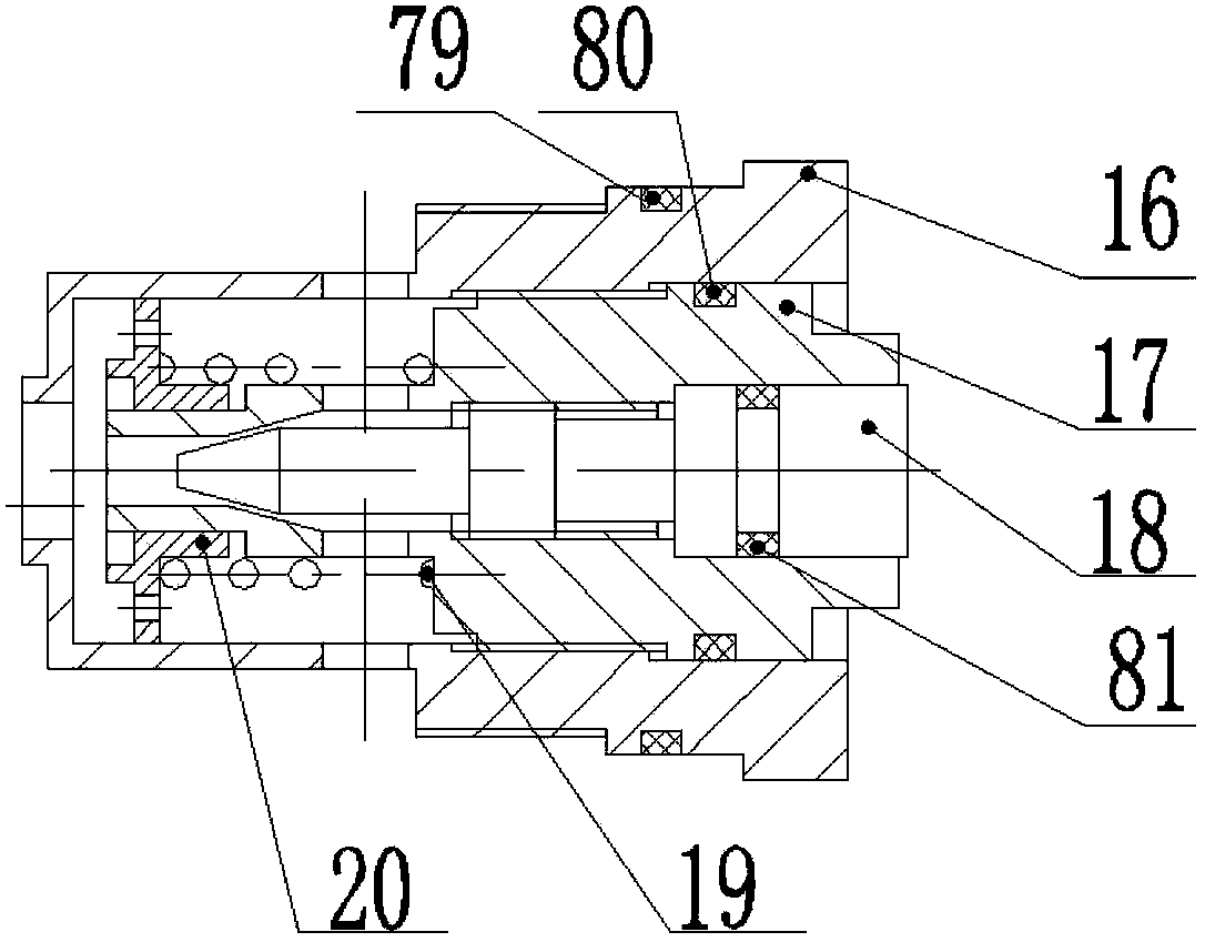
[0039] refer to figure 1 , the high-low speed two-way damping adjustable mechanical shock absorber of the present invention includes the original shock absorber piston upstroke limit block 1, the middle cylinder fixing ring 2, the original shock absorber piston assembly 3, the oil storage cylinder 4, the middle Cylinder 5, piston cylinder 6, bypass valve body 7, tension bypass valve 77, compression bypass valve 78, piston cylinder bottom valve assembly 21 and shock absorber lower fixing ear assembly 22; where: tension bypass The valve 77 has the same structure as the compression bypass valve 78 .

[0040] The original shock absorber piston upstroke limiting block 1 is fitted on the piston rod 72 in the original shock absorber piston assembly 3 through its inner hole to form a sliding fit. The cylindrical surface is in contact with the end surface and the inner cylindrical su...


PUM


Abstract

The invention discloses a high / low speed bidirectional damping adjustable mechanical damper which comprises an original damper piston upper stroke limiting block, an original damper piston assembly, an oil storage cylinder, a middle cylinder, a piston cylinder, a bypass valve body, a piston cylinder bottom valve assembly, a damper lower fixing lug assembly, an stretch bypass valve and a compression bypass valve, wherein the original damper piston upper stroke limiting block is arranged at the upper ends of the oil storage cylinder and the piston cylinder and is mounted at the upper end of the middle cylinder through a middle cylinder fixing ring, a piston body and a piston rod of the original damper piston assembly and the piston cylinder are in sliding connection with the original damper piston upper stroke limiting block, the bypass valve body is sleeved on the lower end of the piston cylinder, the lower ends of the oil storage cylinder and the middle cylinder are fixedly connected with the upper end of the bypass valve body, the piston cylinder bottom valve assembly is fixedly connected with the lower end of the piston cylinder, the damper lower fixing lug assembly is welded and fixed to the lower end of the bypass valve body through an oil storage cylinder lower end cover in the damper lower fixing lug assembly, and the stretch bypass valve and the compression bypass valve are arranged in the bypass valve body and are in threaded connection.

Description

technical field [0001] The invention relates to a mechanical shock absorber with adjustable damping applied to a commercial vehicle, more specifically, the invention relates to a high-low speed two-way adjustable mechanical shock absorber with damping applied to the suspension of a commercial vehicle. Background technique [0002] The suspension system of the vehicle is responsible for alleviating the impact of the road surface and attenuating the vibration of the vehicle body. The suspension is generally composed of guiding mechanisms, elastic elements, shock absorbers and other parts. Among them, the shock absorber is responsible for consuming vibration energy and attenuating the vibration amplitude. For mechanical shock absorbers, when the vehicle encounters an uneven road surface, the suspension moves up and down, the piston of the shock absorber reciprocates in the piston cylinder, and the liquid in each chamber flows through the valve system and the valve system in the...

Claims


Application Information

Patent Timeline
Patent Type & Authority Patents(China)
IPC IPC(8): F16F9/18F16F9/34
Inventor 李静韩佐悦程超黄剑锋
Owner JILIN UNIV
Why Eureka
Try Eureka