Dynamic displacement collecting system based on vehicle-mounted CAN bus

A CAN bus, dynamic displacement technology, applied in the direction of using electrical devices, measuring devices, instruments, etc., can solve problems such as difficulty in sharing collected data, failure to realize real-time transmission and sharing of measurement results, and difficulty in reflecting the dynamic characteristics of vehicle suspension. Displacement data accurate effect

Active Publication Date: 2014-06-04
TSINGHUA UNIV
View PDF4 Cites 8 Cited by
  • Summary
  • Abstract
  • Description
  • Claims
  • Application Information

AI Technical Summary

Problems solved by technology

However, due to the difference between the characteristics after assembly and the decomposition characteristics, the suspension deformation (displacement) of the whole vehicle cannot be equivalent to the simple combination of the decomposed suspension springs, which makes it difficult to reflect the dynamics of the vehicle suspension on the real vehicle characteristic
In addition, the existing methods of measuring deformation have not realized the real-time transmission and sharing of measurement results
In addition, the suspensions of many vehicles are independent suspensions, so that there are relatively many suspension objects that need to be measured and collected at the same time. Only using traditional measurement methods can not only collect multiple channels at the same time, but also make it difficult to share the collected data.
[0004] In addition, the same problem exists for the measurement of length, size, height, fluid level and other deformation quantities related to the stability of vehicle operation

Method used


Image

  • Dynamic displacement collecting system based on vehicle-mounted CAN bus
  • Dynamic displacement collecting system based on vehicle-mounted CAN bus
  • Dynamic displacement collecting system based on vehicle-mounted CAN bus

Examples


Embodiment Construction

[0027] In order to make the object, technical solution and advantages of the present invention clearer, the present invention will be further described in detail below in conjunction with the accompanying drawings.

[0028] The dynamic displacement acquisition system based on the vehicle CAN bus of this embodiment includes: a plurality of sensors installed on the vehicle components to be tested, and a dynamic displacement acquisition device connected to each sensor. Wherein, each sensor collects the dynamic displacement information of the component to be tested during the running of the vehicle, and the component to be tested is a component that may affect the stability of the vehicle operation.

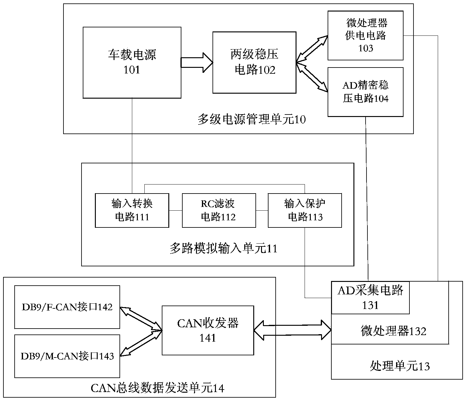
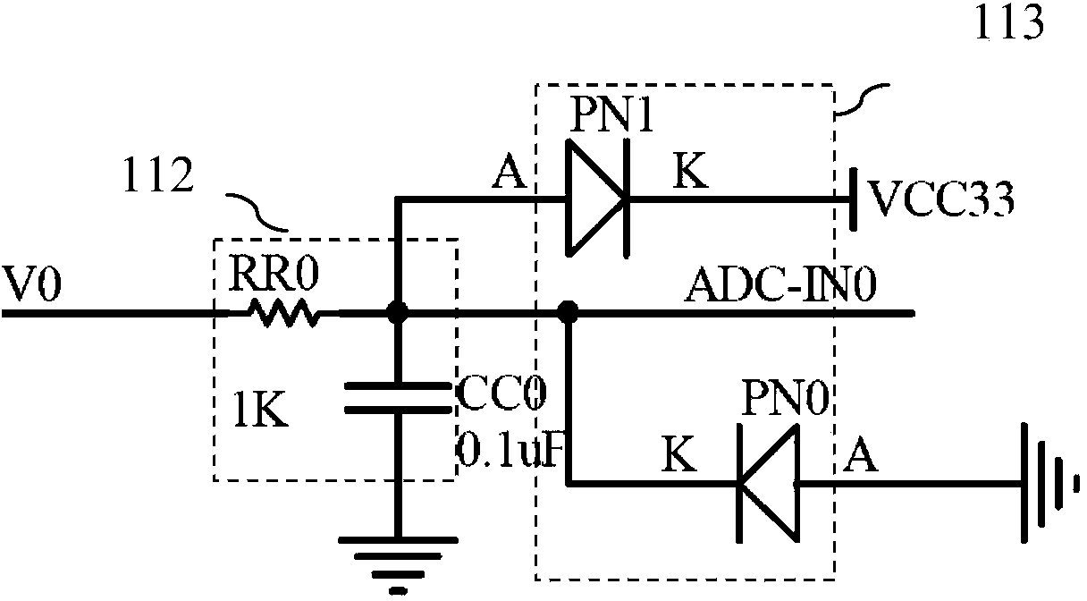
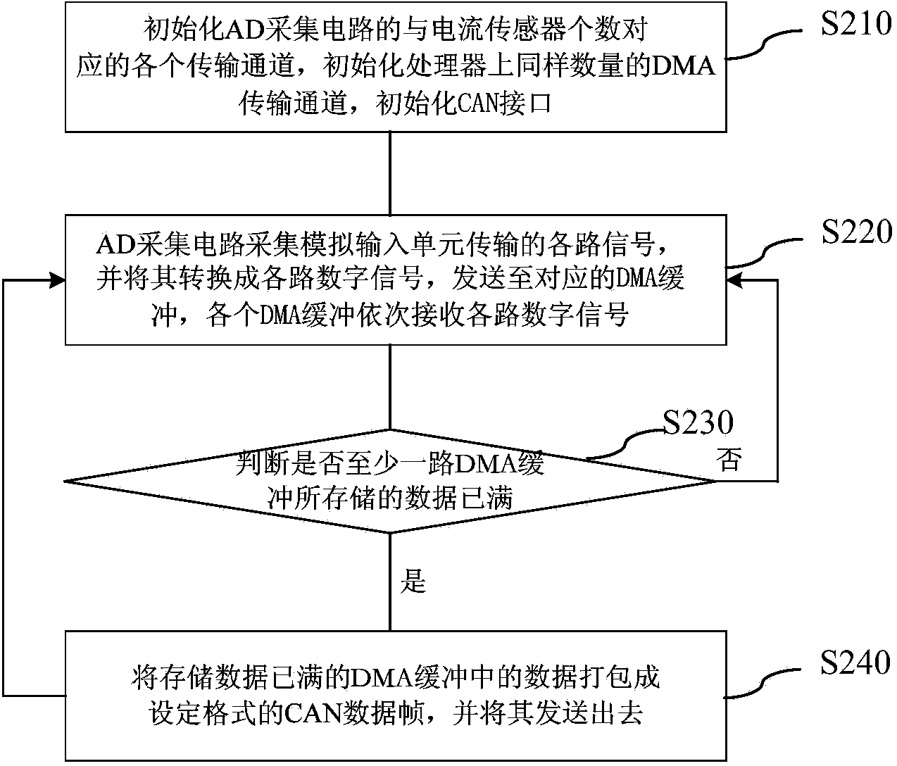
[0029] figure 1 is a schematic structural diagram of a dynamic displacement acquisition device according to an embodiment of the present invention. Combine below figure 1 The dynamic displacement acquisition device will be described in detail.

[0030] From figure 1 It can be see...


PUM


Abstract

The invention discloses a dynamic displacement collecting system based on a vehicle-mounted CAN bus. The dynamic displacement collecting system comprises a plurality of sensors arranged on a component, to be detected, of a vehicle and dynamic displacement collecting equipment connected with the sensors, the sensors are used for collecting the dynamic displacement information of the component to be detected, the equipment comprises a multipath analog input unit, a processing unit and a CAN bus data sending unit, the multipath analog input unit is used for respectively carrying out signal conversion on various paths of dynamic displacement information collected by the sensors, the processing unit is used for receiving the converted signals, digital processing is carried out on the received signals, the signals are sent out, the CAN bus data sending unit is used for receiving data sent by the processing unit, and the data are shared to a vehicle-mounted network through the CAN bus. According to the system, the displacement of a certain component of the vehicle is used as one part of the whole vehicle to be measured, the displacement data are shared through the CAN bus, the vehicle or other CAN bus equipment can read the displacement data conveniently, and accurate data are provide for later vehicle maintenance.

Description

technical field [0001] The invention relates to the fields of automobile active safety and vehicle communication, in particular to a dynamic displacement acquisition system based on vehicle CAN bus. Background technique [0002] The local displacement of the vehicle often has a very important effect on the handling stability of the vehicle. For example, for heavy-duty vehicles with frequent accidents, the displacement of the suspension is related to the safe handling of the vehicle. [0003] For traditional suspension measurement methods, it is mainly the measurement of a single suspension spring or the measurement of a disassembled vehicle suspension part. However, due to the difference between the characteristics after assembly and the decomposition characteristics, the suspension deformation (displacement) of the whole vehicle cannot be equivalent to the simple combination of the decomposed suspension springs, which makes it difficult to reflect the dynamics of the vehic...

Claims


Application Information

Patent Timeline
Patent Type & Authority Applications(China)
IPC IPC(8): G01B7/02
Inventor 姚丹亚魏恒黄何
Owner TSINGHUA UNIV
Why Eureka
Try Eureka