Microstrip Array Antenna with Low Radar Cross Section

A technology of radar cross-section and microstrip array, which is applied in antennas, antenna arrays, resonant antennas, etc., can solve the problems of high radar cross-section and lack of scattering characteristics of antennas, and reduce radar cross-section, overcome poor scattering characteristics, and overcome antenna gain Falling effect

Active Publication Date: 2016-06-29
XIDIAN UNIV
View PDF4 Cites 4 Cited by
  • Summary
  • Abstract
  • Description
  • Claims
  • Application Information

AI Technical Summary

Problems solved by technology

figure 1 An existing four-element microstrip antenna is given, and four equally spaced square radiation elements with a side length of 13.72 mm are printed on the front of the dielectric material board, as shown in figure 1 As shown in (a); the reverse side is printed with a rectangular metal floor with a length of 120mm and a width of 30mm, such as figure 1 As shown in (b), the coaxial connector is fed through the opening on the radiating unit and the metal floor. This antenna has good radiation characteristics, but in order to ensure the radiation characteristics of the antenna, the metal floor must be larger than the size of the radiating unit. Therefore, the radar cross section of the antenna is very high and does not have good scattering characteristics

Method used


Image

  • Microstrip Array Antenna with Low Radar Cross Section
  • Microstrip Array Antenna with Low Radar Cross Section
  • Microstrip Array Antenna with Low Radar Cross Section

Examples


Embodiment 1

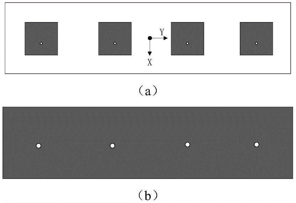
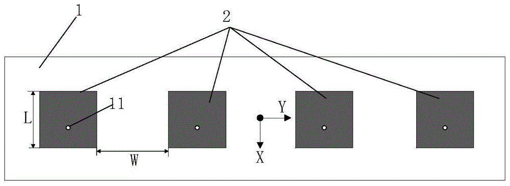
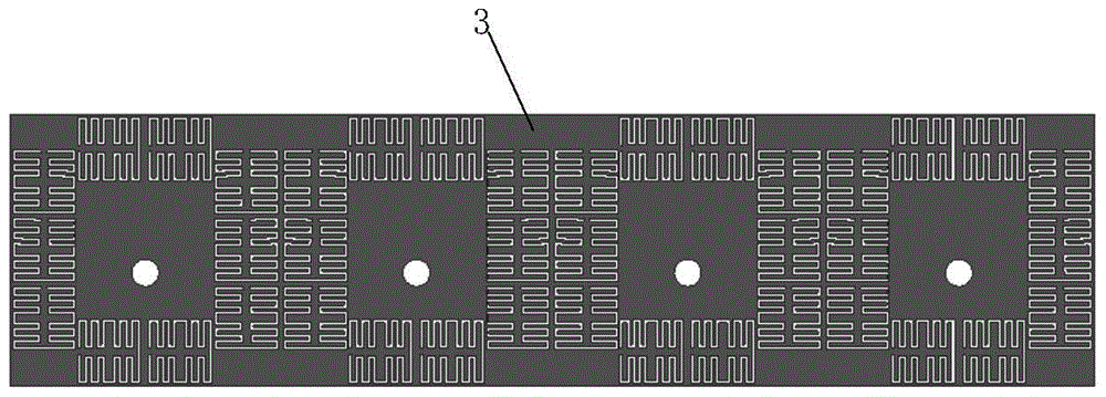
[0037] Four radiating units 2 distributed at equal intervals are printed on the front of the dielectric material plate 1 in a line, and the interval between the radiating units is W=30mm. The rectangular metal plate 3 is printed on the back of the dielectric material plate 1, and the rectangular metal plate 3 is provided with four rectangular areas corresponding to the radiation unit, and there are four complementary split resonant rings distributed around each rectangular area, that is, the entire rectangular metal plate A total of 16 complementary split resonant rings are distributed on the top. Among them, one complementary split resonant ring is distributed above the line segment AB and one complementary split resonant ring is distributed below the line segment CD, and one complementary split resonator ring is distributed on the left side of the line segment AC and the right side of the line segment BD, and the projection distance of each complementary split resonant ring f...

Embodiment 2

[0039] Four radiating units 2 distributed at equal intervals are printed on the front of the dielectric material plate 1 in a line, and the interval between the radiating units is W=30mm. The rectangular metal plate 3 is printed on the back of the dielectric material plate 1, and the rectangular metal plate 3 is provided with four rectangular areas corresponding to the radiation unit, and there are six complementary split resonant rings distributed around each rectangular area, that is, the entire rectangular metal plate A total of 24 complementary split resonant rings are distributed on the top. Among them, one complementary split resonant ring is distributed above the line segment AB and one complementary split resonant ring is distributed below the line segment CD, and two complementary split resonant rings are distributed on the left side of the line segment AC and the right side of the line segment BD respectively, and the interval between the two complementary split reson...

Embodiment 3

[0041] Four radiating units 2 distributed at equal intervals are printed on the front of the dielectric material plate 1 in a line, and the interval between the radiating units is W=30mm. The rectangular metal plate 3 is printed on the back of the dielectric material plate 1. Four rectangular areas corresponding to the radiation unit are arranged on the rectangular metal plate 3. There are ten complementary split resonant rings distributed around each rectangular area, that is, the entire rectangular metal plate A total of 40 complementary split resonant rings are distributed on the top. Among them, two complementary split resonant rings are respectively distributed above the line segment AB and below the line segment CD, and the interval between the two resonant rings is L3=0.9mm, and the projection distance from the radiation unit is L2=1.0mm; on the left side of the line segment AC Three complementary split resonant rings are respectively distributed on the right side of th...


PUM


Abstract

The invention discloses a microstrip array antenna with a low radar cross section. The microstrip array antenna mainly overcomes the defects that an existing microstrip array antenna is high in radar cross section, radiation and scattering characteristics can not be guaranteed at the same time. The antenna comprises a dielectric material plate (1), a radiation unit (2), a metal floor (3) and a coaxial connector (4). The radiation unit and the metal floor of the antenna are printed on the two sides of the dielectric material plate (1) respectively, the metal floor (3) is provided with n complementary split ring resonators (31) distributed around the metal floor under the radiation unit (2), each complementary split ring resonator is of a mirror image symmetric structure formed by an S-shaped bent groove line section, the outline of the periphery of each complementary split ring resonator is square, openings are reserved, and resonant frequency is the same as the work frequency of the array antenna. The antenna has the advantages of being stable in radiation performance, low in radar cross section, simple in structure and easy to process, and can serve as an array antenna on low-radar cross section equipment.

Description

technical field [0001] The invention belongs to the technical field of antennas, in particular to an array antenna, which can ensure that the antenna has good scattering characteristics under the premise of maintaining good radiation performance. For antennas that require both radiation and scattering characteristics, this technology is of great practical value. Background technique [0002] In today's communication field, the signal transmitting and receiving system is the most important part of the entire communication platform, the antenna is the core part of the system, and the radiation characteristics and scattering characteristics are the main indicators to measure the excellent performance of the antenna. The key to improving the scattering characteristics is how to reduce the radar cross section, and the radar cross section is the most basic parameter in the scattering characteristics. It refers to a measure of the target's return power in a given direction under th...

Claims


Application Information

Patent Timeline
Patent Type & Authority Patents(China)
IPC IPC(8): H01Q1/48H01Q9/06H01Q21/00
Inventor 刘英贾永涛郝玉文龚书喜刘虎王辉
Owner XIDIAN UNIV
Why Eureka
Try Eureka