Improved method of detecting wear of a tyre

A tire and tread pattern technology, applied in tire measurement, tire parts, tire tread/tread pattern, etc., can solve problems such as false warnings

Active Publication Date: 2014-06-04
MICHELIN & CO CIE GEN DES ESTAB MICHELIN
View PDF4 Cites 0 Cited by
  • Summary
  • Abstract
  • Description
  • Claims
  • Application Information

AI Technical Summary

Problems solved by technology

[0006] However, under certain conditions, especially under certain conditions of speed and road surface conditions, the warning will be falsely issued
Specifically, it was found that the spectrum selected by the prior art method is not that of the Dirac comb function produced by the wear indicator

Method used


Image

  • Improved method of detecting wear of a tyre
  • Improved method of detecting wear of a tyre
  • Improved method of detecting wear of a tyre

Examples


Embodiment Construction

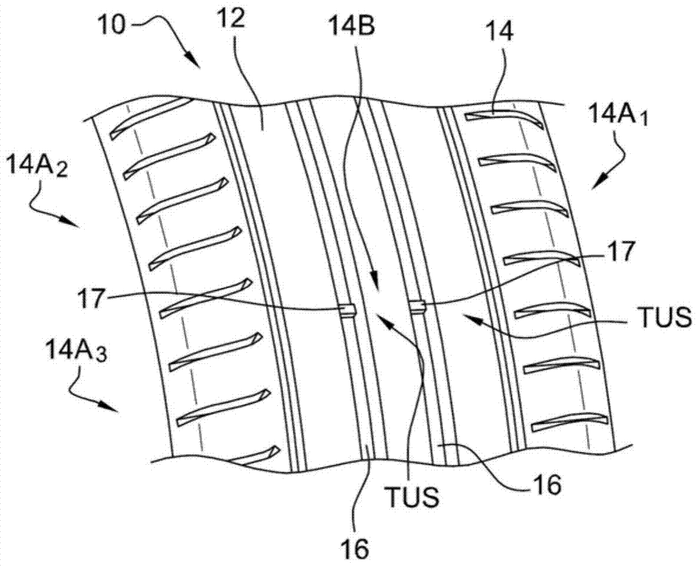
[0053] image 3 The tire is shown in a new condition, indicated by the general reference numeral 10 . The tire 10 is for a passenger vehicle. Tire 10 is essentially a solid body of rotation about an axis.

[0054] Tire 10 includes a tread 12 of substantially annular shape 12 having a tread pattern 14 on its outer surface. The tread pattern includes a first tread pattern element 14A and a second tread pattern element 14B.

[0055] The first tread pattern element 14A comprises circumferentially distributed circumferential portions 14A around an axis of rotation. 1 ,14A 2 ,14A 3 ,...,14A 75 , in this case number seventy-five. 14A per part i With the choice of patterns from a group of several different patterns (typically three or four patterns). The first element 14A comprises two parallel circumferential grooves 16 cut into the surface of the tire, the circumferential grooves 16 having a predetermined depth H when the tire 10 is new. Therefore, each section 14A i A ci...


PUM


Abstract

During the course of the method of detecting wear on a tyre comprising pattern elements capable of generating first and second acoustic footprint noises (BEAI, BEA2), one of the first or second acoustic footprint noises (BEAI, BEA2) being characteristic of the wear of the tyre, there are selected, from the frequency spectrum of an acquired acoustic signal, a parent frequency spectrum capable of forming the frequency spectrum of one of the first or second acoustic footprint noises (BEAI, BEA2) and a child frequency spectrum capable of forming the frequency spectrum of the other of the first or second acoustic footprint noises (BEAI, BEA2). Two confidence indexes called detection confidence indexes are determined. If each detection confidence index satisfies a predetermined condition, a tyre wear detection warning is issued.

Description

technical field [0001] The invention relates to a method of detecting the wear of a tyre. Particularly, but not exclusively, for use in tires for all types of road vehicles including passenger vehicles and heavy goods vehicles. Background technique [0002] A method of detecting the wear of a tire is known from document WO 2011 / 067535. The tire includes a plurality of acoustic wear indicators uniformly distributed around the circumference of the tire and above a predetermined radial wear threshold emitting an acoustic footprint noise having a frequency spectrum comprising a Dirac comb function (peigne des Dirac) multiple fundamental frequency components. The fundamental frequency components of the comb function are uniformly distributed in frequency; that is, the components forming each pair of adjacent components of the comb function are spaced from each other in frequency by a substantially constant frequency difference. [0003] During the method, an acoustic signal is...

Claims


Application Information

Patent Timeline
Patent Type & Authority Applications(China)
IPC IPC(8): B60C11/24
CPCG01M17/025B60C2019/006B60C11/24B60C2019/007B60C11/243B60C11/03B60C11/246B60C11/0318Y10T152/10027
Inventor A·帕蒂勒A·迪克卢
Owner MICHELIN & CO CIE GEN DES ESTAB MICHELIN
Why Eureka
Try Eureka