Antenna device and electronic device

An antenna device and antenna coil technology, which is applied to antennas, loop antennas, and antenna components, etc., can solve the problem of the reader being unable to communicate, and achieve the effect of stable communication.

Active Publication Date: 2014-06-04
MURATA MFG CO LTD
View PDF7 Cites 13 Cited by
  • Summary
  • Abstract
  • Description
  • Claims
  • Application Information

AI Technical Summary

Problems solved by technology

[0003] When such an antenna for non-contact communication is mounted on the back of a metal part, since the magnetic field is shielded by the metal part, communication with a reader / writer etc. which is on the opposite side of the antenna with respect to the metal part cannot be performed.

Method used


Image

  • Antenna device and electronic device
  • Antenna device and electronic device
  • Antenna device and electronic device

Examples


no. 1 Embodiment approach 》

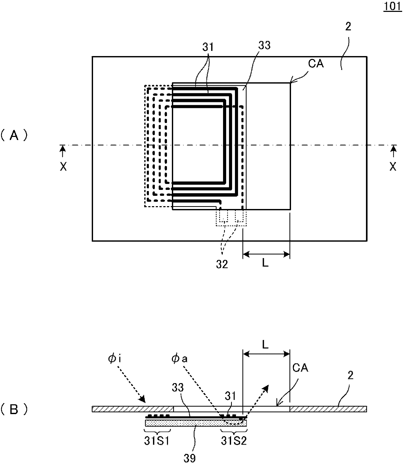
[0045] refer to Figure 1 to Figure 3 The antenna device 101 according to the first embodiment will be described.

[0046] figure 1 (A) is a plan view of the antenna device 101 according to the first embodiment, figure 1 (B) is figure 1 (A) Cross-sectional view of part X-X. Among them, in figure 1 (A), figure 1 In (B), only the configuration of the main part is shown.

[0047] This antenna device 101 includes an antenna coil 31 , a magnetic sheet 39 , and a metal member 2 . The antenna coil 31 is formed on a flexible base material 33 . The antenna coil 31 is wound in a ring shape or a helical shape with the winding center portion serving as a coil opening, and both ends are taken out as connecting portions 32 . In addition, although detailed illustration is omitted, portions where the conductors of the antenna coil 31 overlap and the like are formed on both surfaces of the flexible base material 33 through through holes provided in the flexible base material 33 . ...

no. 2 Embodiment approach 》

[0076] refer to Figure 4 , Figure 5 The antenna device 102 according to the second embodiment will be described.

[0077] Figure 4 (A) is a plan view of the antenna device 102 according to the second embodiment, Figure 4 (B) is Figure 4 (A) Cross-sectional view of part X-X. in, Figure 4 (A), Figure 4 In (B), only the configuration of the main part is shown.

[0078] This antenna device 102 includes an antenna coil 31 , a magnetic sheet 39 , and a metal member 2 . The antenna coil 31 is formed on the flexible base material 33 . The antenna coil 31 is wound in a ring shape or a helical shape with the winding center portion serving as a coil opening.

[0079] The configurations of the antenna coil 31 , the magnetic sheet 39 and the metal member 2 are the same as those shown in the first embodiment. The difference lies in the shape of the magnetic sheet 39 . In the second embodiment, the magnetic sheet 39 is arranged to spread over substantially the entire area i...

no. 3 Embodiment approach 》

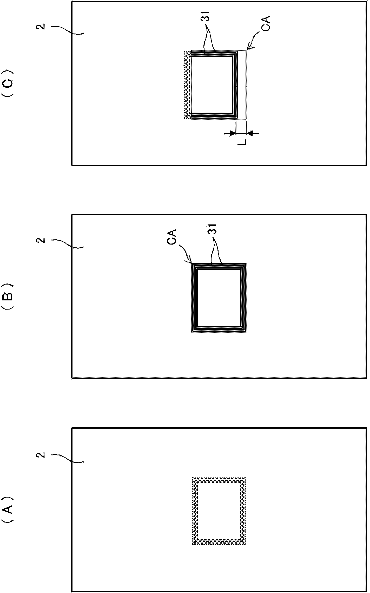
[0083] Image 6 (A) is a plan view of the antenna device 103 of the third embodiment, Image 6 (B) is Image 6 (A) Cross-sectional view of part X-X. in, Image 6 (A), Image 6 In (B), only the configuration of the main part is shown.

[0084] This antenna device 13 is the same as that in the second embodiment Figure 4 Unlike the illustrated antenna device 102 , the magnetic sheet 39 is provided only in the opening CA of the metal member 2 in plan view. Others are the same as the antenna device 102 of the second embodiment.

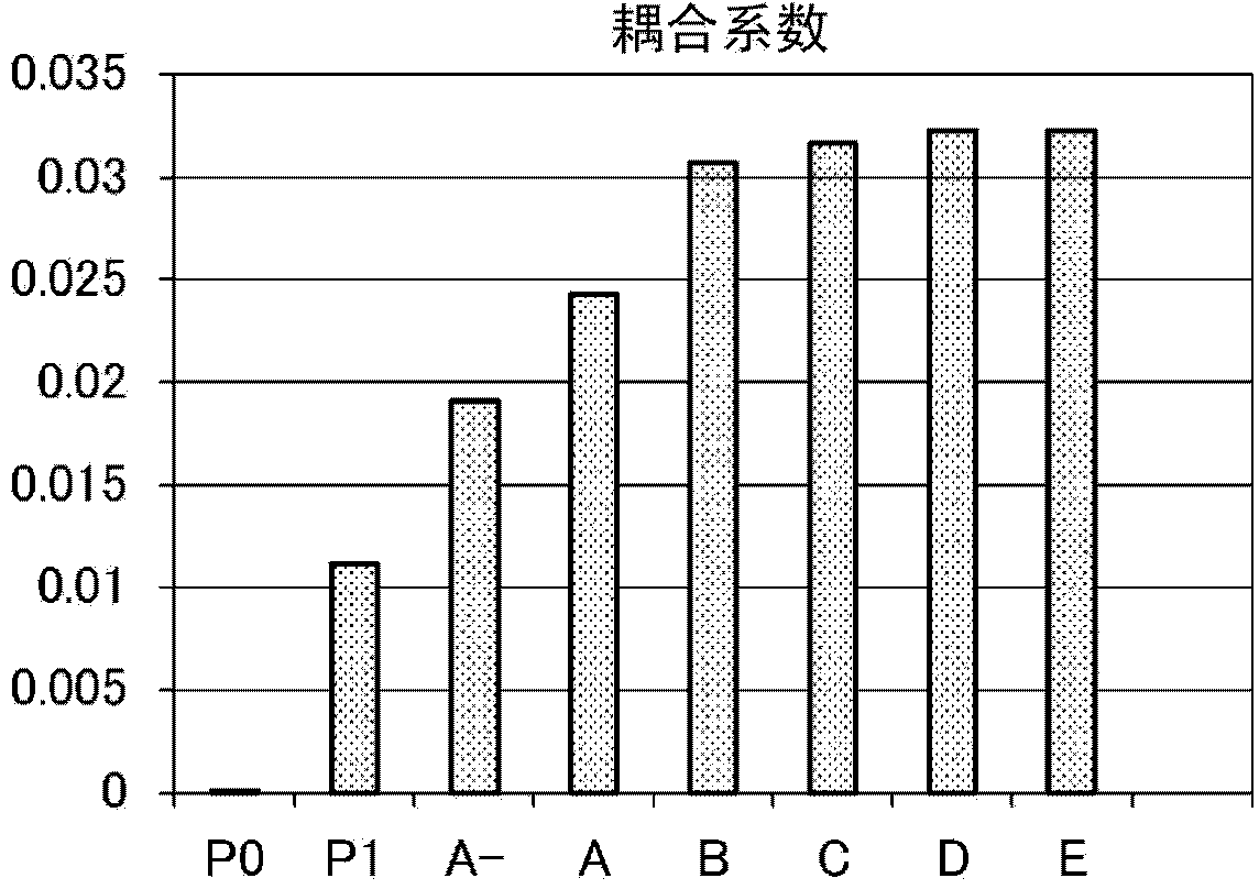
[0085] Figure 7 It is a graph obtained by simulation to obtain the coupling coefficient of the antenna device according to the third embodiment. Figure 7 "B2" in the figure is the characteristic of the antenna device 102 shown in the second embodiment, and "B3" is the characteristic of the antenna device 103 shown in the third embodiment. The conditions for obtaining the coupling coefficient are the same as those in the first embodiment.

[00...


PUM


Abstract

This antenna device (101) is provided with an antenna coil (39), a magnetic sheet (39) and a metal member (2). The antenna coil (31) is formed on a flexible substrate (33). The antenna coil (31) is wound in a loop or spiral with the winding center as a coil open part. The magnetic sheet (39) is arranged on the back surface of the flexible substrate (33). A rectangular opening (CA) is formed on the metal member (2), and the antenna coil (31) is exposed from the opening (CA) of the metal member (2). A first side (31S1) of the antenna coil is hidden by the metal member (2), and the second side (31S2) and a portion of the coil open part are exposed through the opening (CA), so the flux phia is linked to the second side (31S2).

Description

technical field [0001] The present invention relates to an antenna device used in an RFID system and a short-range wireless communication system for communicating with a counterpart device via an electromagnetic field signal, and an electronic device including the antenna device. Background technique [0002] In recent years, in non-contact communication systems using expanded RFID systems, short-range wireless communication systems, etc., in order to communicate between portable electronic devices such as mobile phones, or between portable electronic devices and readers, Each device is equipped with an antenna for communication. [0003] When such a non-contact communication antenna is mounted on the back surface of a metal member, since the magnetic field is shielded by the metal member, it cannot communicate with a reader / writer or the like on the opposite side of the antenna from the metal member. [0004] On the other hand, Patent Document 1 discloses an antenna device...

Claims


Application Information

Patent Timeline
Patent Type & Authority Applications(China)
IPC IPC(8): H01Q7/06G06K19/07G06K19/077H01Q1/38
CPCH01Q7/06H01Q7/00H01Q1/2225H01Q1/243H01Q1/36
Inventor 伊藤宏充
Owner MURATA MFG CO LTD
Why Eureka
Try Eureka