
Non-electric full-automatic gas-liquid rotary spraying fire extinguishing device for military communication shelter

A fire extinguishing device, fully automatic technology, applied in fire rescue and other directions, can solve problems such as being easily affected by water temperature, increasing workload, valve port closing, etc., achieving remarkable fire extinguishing effect and enhanced reliability

Inactive Publication Date: 2014-06-11
刘泳 +2
View PDF9 Cites 7 Cited by
  • Summary
  • Abstract
  • Description
  • Claims
  • Application Information

AI Technical Summary

Problems solved by technology

[0002] At present, automatic fire extinguishing nozzles are installed in military communication shelters to prevent fires. There are two types of automatic fire extinguishing nozzles: one kind of fire extinguishing nozzle is automatically shattered by heat-sensitive components, and the fire extinguishing function is turned on. However, once this type of automatic fire extinguishing nozzle is turned on, it cannot automatically Stop, it will spray continuously until the main valve is closed, the fire will stop, and the water will continue to spray, which will easily cause waste of water resources. The original parts can be used again, which increases the extra workload; another kind of fire extinguishing nozzle is to use the temperature-sensing characteristics of the memory alloy element to open and close the valve port. The influence of water temperature causes the valve port to close prematurely, which cannot completely achieve the purpose of fire extinguishing. Therefore, it is very important to invent a new type of fire extinguishing device to avoid the above hidden dangers.

Method used


Image

  • Non-electric full-automatic gas-liquid rotary spraying fire extinguishing device for military communication shelter
  • Non-electric full-automatic gas-liquid rotary spraying fire extinguishing device for military communication shelter

Examples


Embodiment Construction

[0016] The specific implementation manner of the present invention will be described below in conjunction with the accompanying drawings.

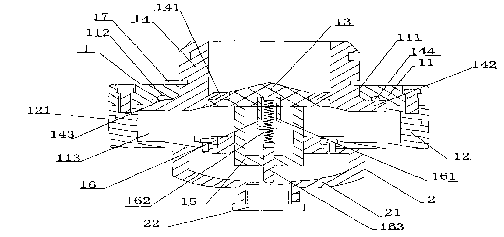
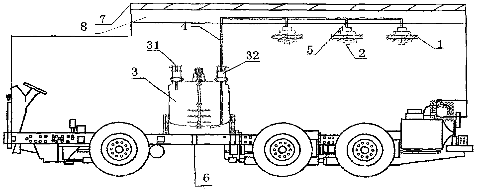
[0017] Such as figure 1 As shown, a non-electric fully automatic gas-liquid rotary spray fire extinguishing device for a military communication shelter, which includes a rotary spray mechanism 1 and a bracket mechanism 2, and the bottom of the rotary spray mechanism 1 is fixedly equipped with a bracket mechanism 2; specifically:

[0018] The rotary spray mechanism 1 includes an upper end cover 11, a lower end cover 12, a flow divider 13, an interface 14, a temperature insulating sleeve 15 and a driving assembly 16; the upper end cover 11 is provided with a through hole 111, and its bottom is provided with an annular groove 112, and the upper end cover 11 and the lower end cover 12 are screwed together to form a material cavity 113; the interface 14 is installed in the through hole 111, and the interface 14 is snapped together with the uppe...


PUM


Abstract

The invention discloses a non-electric full-automatic gas-liquid rotary spraying fire extinguishing device for a military communication shelter. The non-electric full-automatic gas-liquid rotary spraying fire extinguishing device comprises a rotary spraying mechanism and a bracket mechanism, wherein a bracket mechanism is fixedly arranged at the bottom of the rotary spraying mechanism; the rotary spraying mechanism comprises an upper end cover, a lower end cover, a flow divider, a connection opening, a heat insulation sleeve and a driving component. The non-electric full-automatic gas-liquid rotary spraying fire extinguishing device for the military communication shelter is suitable for places such as the military communication shelter, does not need power driving and can be automatically switched on and switched off according to the fixed characteristics of a memory alloy; the memory alloy is separated from the outside through the heat insulation sleeve, so that the phenomenon that a memory alloy spring switches off a sprayer too early because the temperature of a fire extinguishing agent is too low is avoided; the device can be quickly started, and all-round spraying is realized; the fire extinguishing effect is outstanding.

Description

technical field [0001] The invention relates to a rotary spray device, in particular to a non-electric fully automatic gas-liquid rotary spray fire extinguishing device for a military communication shelter. Background technique [0002] At present, automatic fire extinguishing nozzles are installed in military communication shelters to prevent fires. There are two types of automatic fire extinguishing nozzles: one kind of fire extinguishing nozzle is automatically shattered by heat-sensitive components, and the fire extinguishing function is turned on. However, once this type of automatic fire extinguishing nozzle is turned on, it cannot automatically Stop, it will spray continuously until the main valve is closed, the fire will stop, and the water will continue to spray, which will easily cause waste of water resources. The original parts can be used again, which increases the extra workload; another kind of fire extinguishing nozzle is to use the temperature-sensing charac...

Claims


Application Information

Patent Timeline
IPC IPC(8): A62C3/07A62C35/02
Inventor 刘泳薛旭忠薛博杰
Owner 刘泳
Learn More