
Fixing mechanism for fan blade welding device

A technology of welding equipment and fixing mechanism, which is applied in the direction of welding equipment, auxiliary welding equipment, welding/cutting auxiliary equipment, etc. It can solve the problems of inaccurate welding position, affecting the use of fans, and the inability to realize unified production standardization, etc., and achieve accurate welding position , Welding flexible effect

Inactive Publication Date: 2014-06-11
DEQING ZHENDA ELECTRIC
View PDF6 Cites 2 Cited by
  • Summary
  • Abstract
  • Description
  • Claims
  • Application Information

AI Technical Summary

Problems solved by technology

This type of operation has the following defects: the welding position will be inaccurate during the welding process, thereby affecting the use of the fan; and there is a deviation in the angular position between the blades of different fans and the fan main body, even in the same fan. There are also angle deviations in the blades, which cannot achieve unified production standardization
Moreover, during the welding process, it is necessary to weld and fix the various points of the fan main unit, so it is difficult to solve the problem.

Method used


Image

  • Fixing mechanism for fan blade welding device

Examples


Embodiment Construction

[0009] Combine below figure 1 Specific description embodiment:

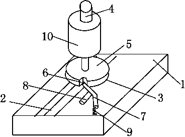
[0010] A fixing mechanism for fan blade welding equipment, characterized in that the fixing mechanism of the fan blade welding equipment includes a base 1, a chute 2 is opened in the middle of the base 1, and a chute 2 is provided on the base 1 Platform 3, the platform 3 can slide in the chute 2, the platform 3 is provided with a column 4, the lower part of the column 4 is connected with a disc 5, the side of the disc 5 Four card slots 6 are provided, and a card bar 7 is hinged on the platform 3, and a pull bar 8 is provided on the side of the card bar 7, and one end of the card bar 7 can be clamped in the card slot 6. , the other end of the clip 7 is connected with a spring 9, and the spring 9 is fixed on the platform 3; the middle of the column 4 is provided with a fan positioning seat 10, and the fan positioning seat 10 is connected with the disc 5 phase fixed.

[0011] During specific use, the fan main bod...


PUM


Abstract

The invention belongs to the technical field of fan appliances and particularly relates to a fixing mechanism for a fan blade welding device. The fixing mechanism comprises a pedestal, wherein a chute is formed in the middle of the pedestal, a platform is arranged on the pedestal, and a spring is connected to the other end of a clamping strip and is fixed on the platform; a fan positioning seat is arranged in the middle of an upright post and is fixed with a disc. According to the fixed mechanism, a fan engine can be well fixed and positioned, so that the welding position between the fan engine and blades is accurate, and a fan can be flexibly welded.

Description

technical field [0001] The invention belongs to the technical field of fan appliances, and in particular relates to a fixing mechanism of fan blade welding equipment. Background technique [0002] In the production process of the micro-motor fan, the stator of the motor is firstly produced, then the production of the micro-motor is completed, and finally the micro-motor and the blades are connected together to complete the production of the entire micro-motor fan. When making a fan, the blades need to be welded to the fan main body. However, the welding method currently used is generally to manually hold the blades and align them with the position of the main fan, and then use a welding gun for welding. This type of operation has the following defects: the welding position will be inaccurate during the welding process, thereby affecting the use of the fan; and there is a deviation in the angular position between the blades of different fans and the fan main body, even in th...

Claims


Application Information

Patent Timeline
Patent Type & Authority Applications(China)
IPC IPC(8): B23K37/047
CPCB23K37/047
Inventor 蔡忠义熊建军
Owner DEQING ZHENDA ELECTRIC
Learn More