

Automatic welding equipment of plastic case
An automatic welding and box body technology, applied in the field of welding equipment, can solve the problems of low welding quality, many processing procedures, leakage of the box body, etc.
- Summary
- Abstract
- Description
- Claims
- Application Information
AI Technical Summary
Problems solved by technology
Method used
Image

Examples
Embodiment Construction
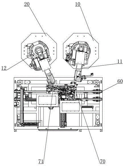
[0022] Such as figure 1 As shown, a plastic box automatic welding equipment includes a control system, a welding device, a conveying device and a fixing device arranged below the welding device, and the welding device, the conveying device and the fixing device are all electrically connected to the control system The welding device includes a weldment clamping mechanism 10 and a thermal mold mechanism 20. A weldment heating structure is provided on one side of the weldment clamping mechanism 10, the conveying device 60 includes a conveyor belt, the fixing device 70 is arranged below the conveyor belt, and the fixing device 70 includes a supporting and fixing mechanism 71 and the lifting mechanism connected with the supporting and fixing mechanism 71. The supporting and fixing mechanism 71 includes a positioning block and a pressing block arranged on the opposite side of the positioning block.
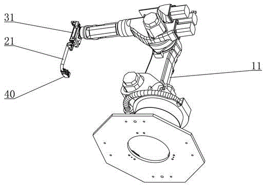
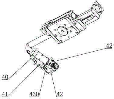
[0023] Such as figure 2 , 3, 4, the weldment clamping mechanism 10 includes a ...
PUM
 Abstract
Description
Claims
Application Information