Washing machine clamping device

The technology of a clamping device and cleaning machine is applied in the direction of workpiece clamping devices, cleaning methods and appliances, chemical instruments and methods, etc., which can solve problems such as inability to judge and equipment damage, and achieve offset prevention, reasonable structure, and avoidance of damage effect

Inactive Publication Date: 2014-06-11
姚典廷
View PDF0 Cites 11 Cited by
  • Summary
  • Abstract
  • Description
  • Claims
  • Application Information

AI Technical Summary

Problems solved by technology

[0002] In the prior art, the disk-shaped workpiece needs to be ensured that its center of circle is on the center line of the cleaning chamber in the pass-through cleaning machine, and the process of the pass-through cleaning machine from workpiece feeding to cleaning chamber positioning and cleaning is fully automated. Since t

Method used


Image

  • Washing machine clamping device
  • Washing machine clamping device
  • Washing machine clamping device

Examples


Example Embodiment

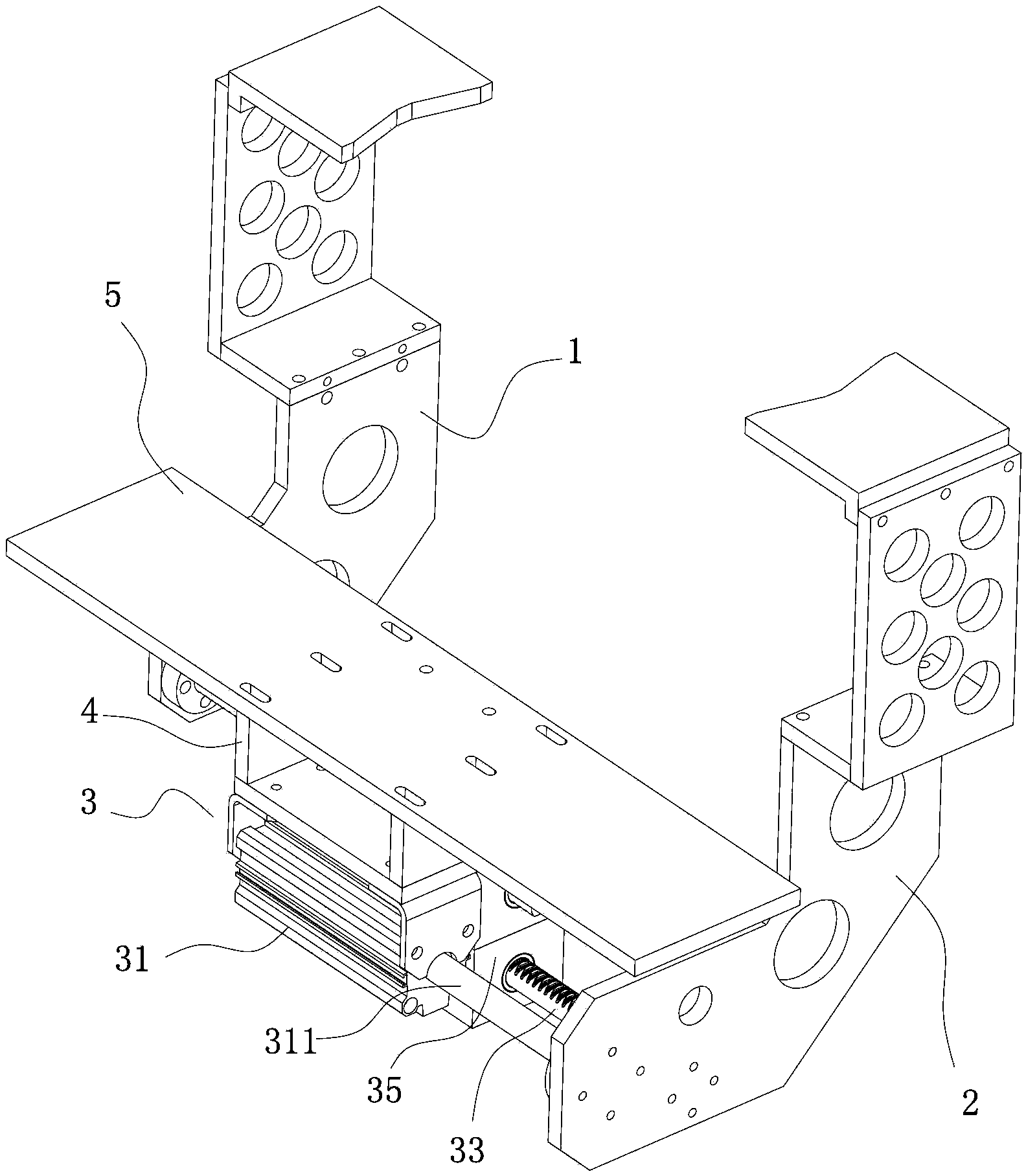
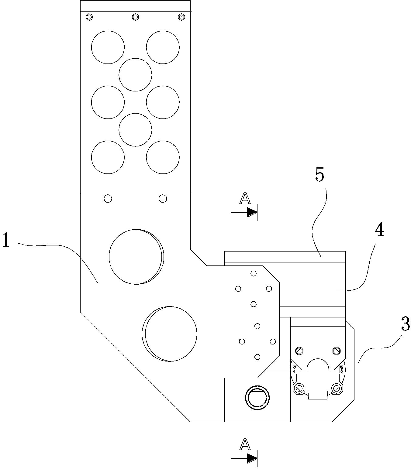
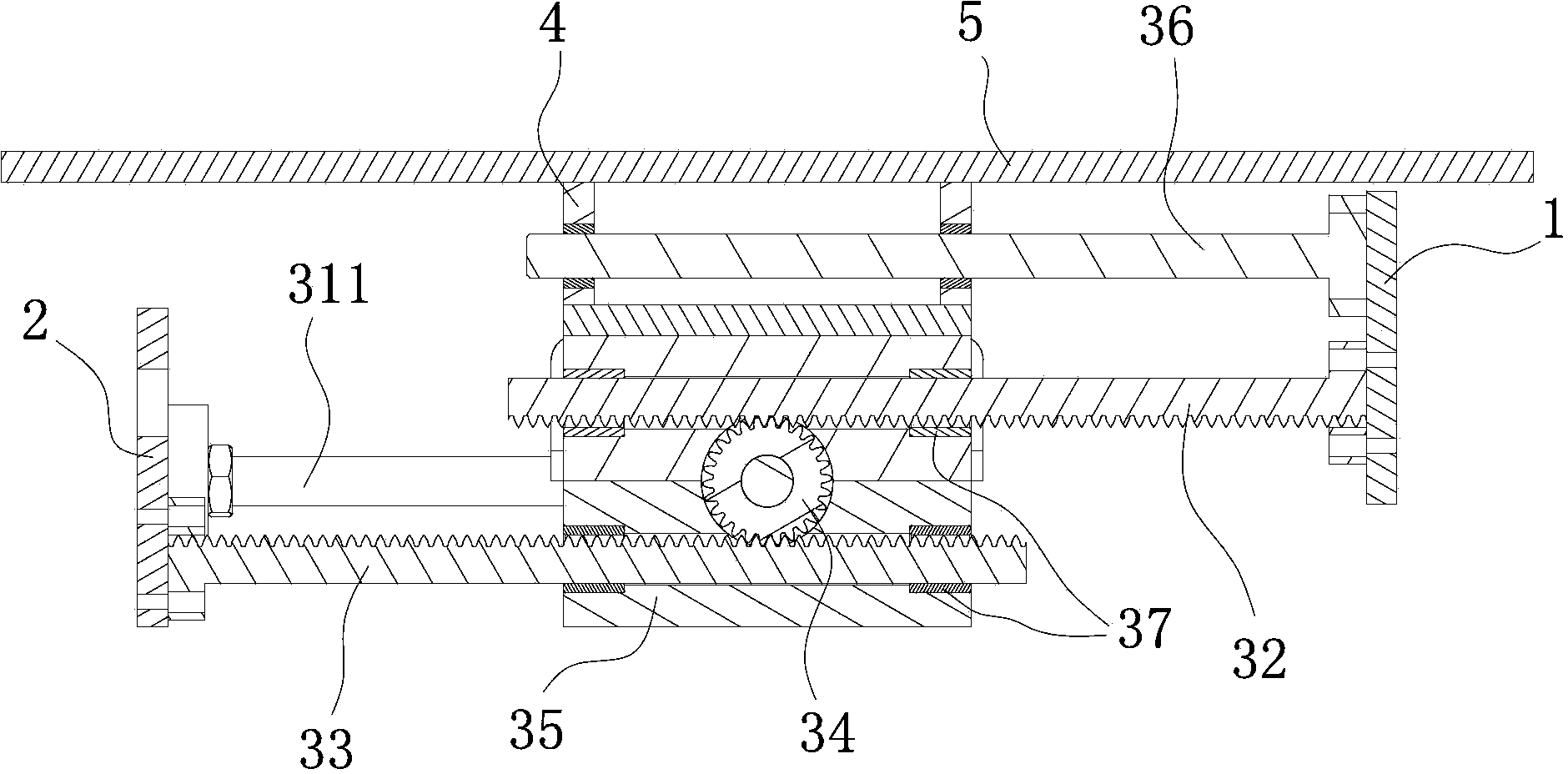
[0014] Example: see Figure 1 to Figure 4 , a cleaning machine clamping device of the present invention, which includes a left clamp 1 and a right clamp 2 for clamping the workpiece to be processed, and between the left clamp 1 and the right clamp 2 An energy A pairing mechanism 3 that enables the left and right clamps 1 and 2 to open or clamp synchronously in a linear direction. The clamping mechanism 3 includes a clamping cylinder 31, a left rack 32, a right rack 33 and a central gear 34. The left and right racks 32 and 33 have the same length, the same tooth size and the same module. The gear 34 is arranged at the center of a housing 35 , the left rack 32 is arranged above the central gear 34 and meshes with the central gear 34 , and the right rack 33 is arranged below the central gear 34 and is in engagement with the central gear 34 . 34 are engaged, the left end of the left rack 32 is fixedly connected to the left clip 1, the right end of the right rack 33 is fixedly con...


PUM


Abstract

The invention discloses a washing machine clamping device which comprises a left clamping piece, a right clamping piece and an opposite clamping mechanism. The opposite clamping mechanism comprises a clamping cylinder, a left rack, a right rack and a center gear. The left rack and the right rack are identical in length, tooth size and modulus. The clamping cylinder is fixed on the outside of a casing, and an output shaft of the clamping cylinder is fixedly connected onto the right clamping piece. The clamping device is reasonable in structure, the left clamping piece and the right clamping piece move synchronously when a workpiece is clamped, the workpiece is located in the middle of the clamping device when the workpiece is in the clamped state, the center of the workpiece and the center of the washing machine are located on the same line, excursion of the position of the workpiece is effectively prevented, device damage is avoided, and wide popularization and application are facilitated.

Description

technical field [0001] The invention relates to the field of clamping technology, in particular to a clamping device for a washing machine. Background technique [0002] In the prior art, the disk-shaped workpiece needs to be ensured that its center of circle is on the center line of the cleaning chamber in the pass-through cleaning machine, and the process of the pass-through cleaning machine from workpiece feeding to cleaning chamber positioning and cleaning is fully automated. Since there is no manual loading, it is impossible to judge whether the workpiece is on the center line of the cleaning room when the workpiece is transported to the cleaning position; if the workpiece is not in place and not on the center line of the cleaning room, it may cause damage to the equipment , or even more serious problems. In order to ensure that the workpiece can be positioned well after entering the cleaning room, a synchronous clamping device has been developed. Contents of the inv...

Claims


Application Information

Patent Timeline
IPC IPC(8): B25B11/00B08B13/00
CPCB25B11/00B08B13/00
Inventor 姚典廷
Owner 姚典廷
Why Eureka
Try Eureka