Al technical title is built by PatSnap Al team. It summarizes the technical point description of the patent document.
A robot finger and under-actuated technology, which is applied in the direction of manipulators, chucks, manufacturing tools, etc., can solve the problems of unrealized closed and stable grasping, no grasping force, and grasping failure.
Inactive Publication Date: 2014-06-11
TSINGHUA UNIV
View PDF7 Cites 18 Cited by
Summary
Abstract
Description
Claims
Application Information
AI Technical Summary
This helps you quickly interpret patents by identifying the three key elements:
Problems solved by technology
Method used
Benefits of technology
Problems solved by technology
[0004] The disadvantage of this device is: when the object does not squeeze the middle finger segment of the device, the end finger segment will return to the initial state of straightening, so the device cannot implement the object grasping that the reaction surface is canceled during the grasping process
For example, if an object is placed on the table, when the finger mounted on the robotic arm is close to the object, the motor will drive the first joint to rotate, and the object will block and squeeze the middle finger, so the rack mechanism will cause the second joint of the finger to bend. But when the mechanical arm leaves the table, the object no longer squeezes the middle finger segment, and the end finger segment will return to the initial state of straightening. The bending of the finger cannot be maintained, so the object falls off and the grasping fails.
On the other hand, although the device achieves an adaptive envelope effect on the shape when grasping objects, it does not generate a grasping force, and thus does not realize force-closed and stable grasping. Envelope to achieve a stable grip
Method used
Image
Click on the blue label to locate the original text in one second.
Reading with bidirectional positioning of images and text.
Examples
Embodiment Construction
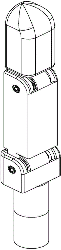
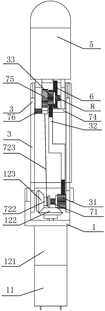
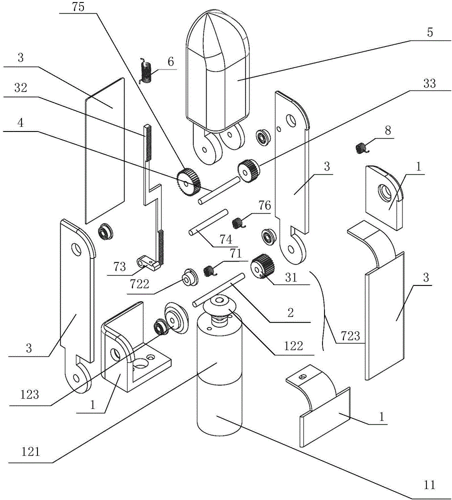
[0032] The specific structure and working principle of the present invention will be further described in detail below in conjunction with the accompanying drawings and embodiments.
[0033] An embodiment of a rack check self-adaptive underactuated robot finger device designed by the present invention, as figure 1 , figure 2 , image 3 , Figure 4 , Figure 5 and Figure 6 As shown, it includes base 1, motor 11, first transmission mechanism 13, proximal joint shaft 2, middle finger section 3, driving gear 31, rack 32, driven gear 33, distal joint shaft 4, terminal finger section 5 and The first spring member 6; the motor 11 is fixedly connected to the base 1, the output shaft of the motor 11 is connected with the input shaft of the first transmission mechanism 12, and the output shaft of the first transmission mechanism 12 is connected with the proximal joint shaft 2, and the The proximal joint shaft 2 is movably sleeved in the base 1, the distal joint shaft 4 is movably...
PUM
Abstract
The invention provides a rack check self-adaptive under-actuated robot finger device, which belongs to the technical field of a robot hand. The rack check self-adaptive under-actuated robot finger device comprises a base, a motor, a first transmission mechanism, a near joint shaft, a middle finger section, a driving gear, a rack, a driven gear, a far joint shaft, a tail-end finger section, a first spring element, a second transmission mechanism, a pawl, a pawl shaft, a racket wheel, a second spring element, a third spring element and a fourth spring element. The rack check self-adaptive under-actuated robot finger device can be installed on a mechanical arm, the counteractive surface removing object grabbing is implemented through being matched with the active movement of the mechanical arm, the self-adaptive capability on the shape and the size of the grabbed objects can be realized, the stable grabbing on the shape sealing and force sealing can be reached during the object grabbing, and the joint recovery stability losing phenomenon caused by vibration interface in the grabbing process can be prevented. The rack check self-adaptive under-actuated robot finger device has the advantages that the structure is simple, the size is small, the weight is light, the manufacturing and maintenance cost is low, and the robot finger device is similar to the fingers of human hands.
Description
technical field [0001] The invention belongs to the technical field of robot hands, in particular to a structural design of a rack check self-adaptive underactuated robot finger device. Background technique [0002] Similar to humans, most functions of anthropomorphic robots are realized through hand manipulation, so the hand structure is an important part of anthropomorphic robots, and its design is one of the key technologies of anthropomorphic robots. In order to increase the anthropomorphism of the hand, more joint degrees of freedom should be designed for the hand. However, in order to reduce the control difficulty of the anthropomorphic robot hand, as well as reduce the volume and weight of the hand, it is necessary to reduce the number of drivers. Certain contradictions, in addition, in order to better grasp the object, it is also necessary for the finger to have a certain degree of adaptability when grasping the object. Underactuated fingers can better achieve the t...
Claims
Application Information
Patent Timeline
Application Date:The date an application was filed.
Publication Date:The date a patent or application was officially published.
First Publication Date:The earliest publication date of a patent with the same application number.
Issue Date:Publication date of the patent grant document.
PCT Entry Date:The Entry date of PCT National Phase.
Estimated Expiry Date:The statutory expiry date of a patent right according to the Patent Law, and it is the longest term of protection that the patent right can achieve without the termination of the patent right due to other reasons(Term extension factor has been taken into account ).
Invalid Date:Actual expiry date is based on effective date or publication date of legal transaction data of invalid patent.