Polyethylene pipe conveying device

A conveying device, polyethylene pipe technology, applied in the direction of tubular objects, applications, household appliances, etc., to improve the quality of the factory and ensure the effect of cutting

Inactive Publication Date: 2014-06-11
XINGHUA DONGXU MACHINERY
View PDF0 Cites 4 Cited by
  • Summary
  • Abstract
  • Description
  • Claims
  • Application Information

AI Technical Summary

Problems solved by technology

[0003] The purpose of the present invention is to solve the technical problem that the polyethylene pipe needs to be output smoothly to ensure that the cut is neat when cutting the polyethylene pipe after forming. It provides a polyethylene pipe conveying device, which is specifically realized by the following technical scheme

Method used


Image

  • Polyethylene pipe conveying device

Examples


Embodiment Construction

[0008] The present invention will be further described below in conjunction with the accompanying drawings and specific embodiments.

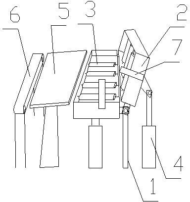
[0009] The polyethylene pipe conveying device includes a frame 1, two overturning frames 2, several conveying rollers 3, a transition plate 5, a conveyor belt 6, a pair of travel switches 7, and two overturning frame drive mechanisms 4, and one side of the two overturning frames 2 The sides are respectively hinged with the frame 1, there are two turning frame driving mechanisms 4 and are respectively connected with the turning frame 2, the conveying rollers 3 are evenly distributed in the turning frame 2, the transition plate 5 is obliquely arranged on one side of the turning frame 2, and the conveyor belt 6 Set on the other side of the transition plate 5, the travel switch 7 is set at the end of the turning frame, so that when the polyethylene pipe touches the travel switch 7, the corresponding production equipment stops outputting the polyethy...


PUM


Abstract

The invention relates to a polyethylene pipe conveying device. The polyethylene pipe conveying device comprises a rack, two overturning frames, a plurality of transfer rollers, a transition plate, a conveyor belt and two overturning frame driving mechanisms, wherein one of the side edges of the two overturning frames is respectively hinged with the rack, the two overturning frame driving mechanisms are respectively connected with the overturning frames, the transfer rollers are uniformly distributed in the overturning frames, the transition plate is obliquely arranged on one side of one overturning frame, and the conveyor belt is arranged on the other side of the transition plate. According to the polyethylene pipe conveying device provided by the invention, the two overturning frames are driven by a hydraulic rod, and in view of polyethylene pipes with different specifications, different angles are formed between the two overturning frames to ensure the stable output of the polyethylene pipes with different specifications, so as to ensure trim notches and improve the outgoing quality.

Description

technical field [0001] The invention relates to a polyethylene pipe conveying device. Background technique [0002] After the polyethylene raw material is mixed with the pigment evenly, it is sent to the corresponding equipment, and various specifications of polyethylene pipes are formed according to the specifications of the tube core. Polyethylene pipes are continuously output from the production equipment. In order to facilitate the subsequent processes and the final delivery, the polyethylene pipes need to be cut to a certain length while being output in a stable posture, and then transferred to other production stations. . Contents of the invention [0003] The purpose of the present invention is to solve the technical problem that the polyethylene pipe needs to be output smoothly to ensure a neat cut when the polyethylene pipe is cut after forming. It provides a polyethylene pipe conveying device, which is specifically realized by the following technical solutions. ...

Claims


Application Information

Patent Timeline
Patent Type & Authority Applications(China)
IPC IPC(8): B29C47/34B29L23/00B29K23/00B29C48/355
CPCB29C48/355B29K2023/06B29L2023/00
Inventor 章志娟
Owner XINGHUA DONGXU MACHINERY
Why Eureka
Try Eureka