
Rotary cindervalve

An ash discharge valve and valve body technology, which is applied in the field of rotary valves, can solve the problem of uneven discharge of the rotary ash discharge valve, and achieve the effect of ensuring the blanking.

Active Publication Date: 2014-06-11
LAIWU IRON & STEEL GRP
View PDF7 Cites 2 Cited by
  • Summary
  • Abstract
  • Description
  • Claims
  • Application Information

AI Technical Summary

Problems solved by technology

[0004] The purpose of the present invention is to provide a rotary ash release valve to solve the problem of uneven output of the rotary ash release valve in the prior art due to the existence of the pressure balance area

Method used


Image

  • Rotary cindervalve

Examples


Embodiment Construction

[0018] The present invention will be described in further detail below in conjunction with the accompanying drawings and specific embodiments.

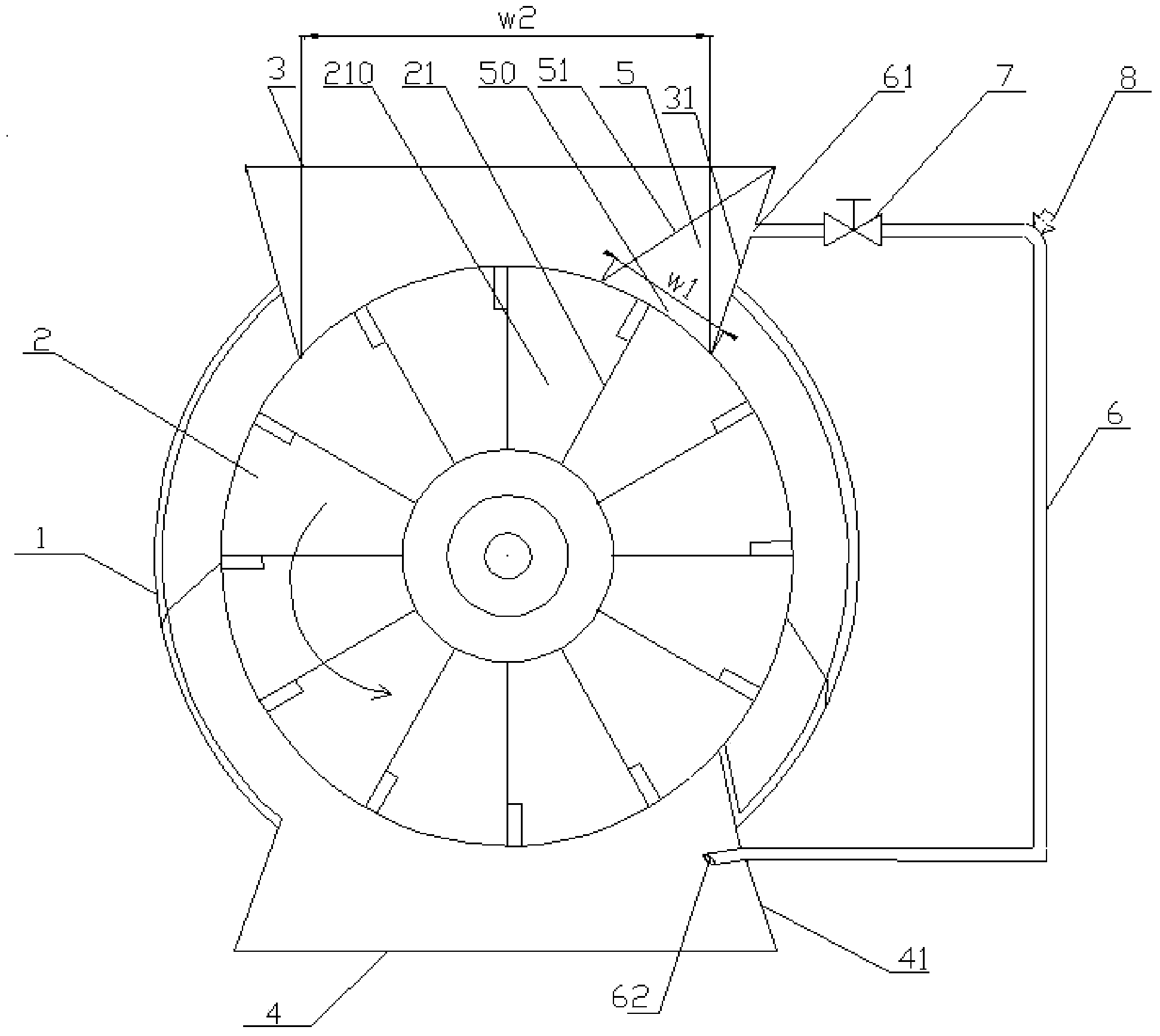
[0019] figure 1 Schematically shows the structure of a preferred embodiment of the present invention, as shown, this preferred embodiment includes a valve seat 1, a valve body 2, a material inlet 3, a material outlet 4, a gas collection chamber 5, and a guide channel 6 Wait.

[0020] Specifically, the valve body 2 is located inside the valve seat 1, and a plurality of baffles 21 are distributed along its circumferential direction on the valve body 2, and the space between adjacent baffles 21 is formed to accommodate powdery materials, such as The grid groove 210 for the dedusted ash formed in the coking process of the coking plant. The material inlet 3 is located on the upper part of the valve seat 1, and it is used to make the powdery material fall into the grid groove 210 of the valve body 2. For example, the material inlet 3 is c...


PUM

PropertyMeasurementUnit
Thicknessaaaaaaaaaa

Abstract

The invention provides a rotary cindervalve, which comprises a valve seat, a valve seat, a receiving port and a discharging port, wherein the valve body is arranged inside the valve seat; a plurality of lattice grooves used for containing powdery materials are distributed in the valve body along the peripheral direction; the receiving port is located in the upper part of the valve seat and is used for enabling the powdery materials to fall into the lattice grooves of the valve body; the discharging port is located in the lower part pf the valve seat and is used for discharging the powdery materials which are contained in the lattice grooves of the valve body. In addition, the rotary cindervalve also comprises a gas collection chamber and a flow guide channel, wherein the gas collection chamber is located at one side, where the valve body is upwards rotated, of the receiving port, and is of a cavity structure with an opening in the lower part, and the opening faces and is close to the lattice grooves of the valve body; one end of the flow guide channel is communicated with the gas collection chamber; the other end of the flow guide channel is used for discharging gas in the gas collection chamber. According to the rotary cindervalve, the flow direction of the gas in the valve can be changed, air bubbles are prevented from forming in a dedusting bin, and the blanking is enabled to be uniform.

Description

technical field [0001] The present invention relates to the technical field of rotary valves, in particular, the present invention particularly relates to a rotary ash discharge valve used in coking dust removal ash humidification equipment. Background technique [0002] At present, the pulse bag filter is commonly used in the coking process of the coking plant, and the circulating fan sucks the dusty air into the filter for gas-solid separation. After the quantity, slowly put it into the humidifier by rotating the ash release valve, add water to moisten it, stir it fully, and then load it into a car for transportation. [0003] The rotation of the rotary ash discharge valve of the dust removal bin has directionality. When the rotary ash discharge valve is running, the dust will enter the humidifier through the downward rotation side of the rotary ash discharge valve, and the air will pass through the upward rotation side of the ash discharge valve. side into the dust chamb...

Claims


Application Information

Patent Timeline
IPC IPC(8): B65G29/02
Inventor 翟瑞津陈勇
Owner LAIWU IRON & STEEL GRP
Learn More