Discharging door

A technology for unloading doors and openings, which is applied to unloading devices, containers, packaging, etc., and can solve problems such as material spillage, material leakage, and poor sealing of door panels

Pending Publication Date: 2021-05-18
SHANTUI JANEOO MACHINERY
View PDF0 Cites 1 Cited by
  • Summary
  • Abstract
  • Description
  • Claims
  • Application Information

AI Technical Summary

Problems solved by technology

The commonly used discharge door in the prior art is a side-by-side door structure composed of two door panels. Due to the harsh working environment of concrete mixing, the door panels are often

Method used


Image

  • Discharging door
  • Discharging door
  • Discharging door

Examples


Embodiment Construction

[0033] In order to enable those skilled in the art to better understand the technical solutions in the present invention, the technical solutions in the embodiments of the present invention will be clearly and completely described below in conjunction with the drawings in the embodiments of the present invention. Obviously, the described The embodiments are only some of the embodiments of the present invention, not all of them.

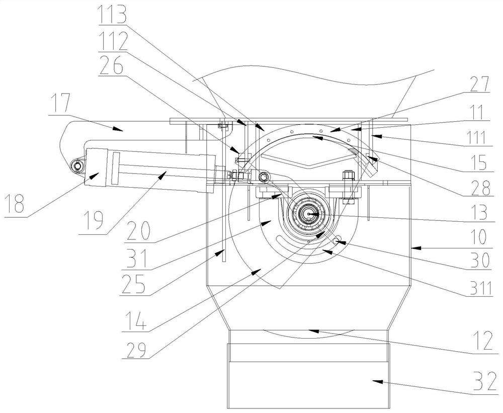
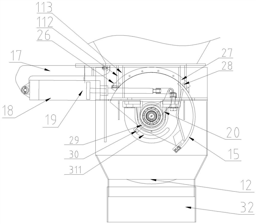
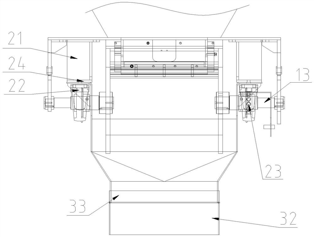
[0034] Please refer to Figure 1-Figure 5As shown, a discharge door includes a shield 10, the top of the shield 10 is provided with a discharge port 11, the bottom of the shield 10 is provided with a discharge port 12, and the side wall of the shield 10 is provided with a rotating shaft 13, Also be provided with arc-shaped door body in guard 10, arc-shaped door body comprises two convex arc-shaped baffles 14 that are arranged in parallel and is located at the arc-shaped door panel 15 between two convex-arc-shaped baffles, and arc-shaped door panel 15 ...


PUM


Abstract

The invention discloses a discharging door. The discharging door comprises a protective cover, a discharging opening is formed in the upper portion of the protective cover, a discharging opening is formed in the lower portion of the protective cover, a rotating shaft is arranged on the side wall of the protective cover, an arc-shaped door body is further arranged in the protective cover, the arc-shaped door body comprises two convex arc-shaped baffles arranged in parallel and an arc-shaped door plate arranged between the two convex arc-shaped baffles, the arc-shaped door plate is matched with the discharging opening on the lower portion of the discharging opening, and therefore when the discharging opening is closed, the arc-shaped door plate is in contact sealing with the discharging opening; and a driving assembly is further arranged on the side wall of the protective cover, one end of the rotating shaft is matched with the power output end of the driving assembly, and the other end of the rotating shaft is connected with the convex arc-shaped baffles, so that the convex arc-shaped baffles are driven to rotate to enable the arc-shaped door plate to open or close the discharging opening. Compared with a traditional discharging door of a double-door structure, the arc-shaped door plate of the discharging door can achieve contact sealing with the discharging opening through rotation, the rotating consistency of the arc-shaped door plate during sealing is good, the defects of material leakage, material scattering and the like between two door plates when a traditional door plate is closed are overcome, and normal discharging is guaranteed.

Description

technical field [0001] The invention relates to the technical field of stirring equipment, in particular to a discharge door. Background technique [0002] The concrete hopper is a commonly used discharge device in concrete mixing production. The mixed concrete flows into the concrete transport vehicle through the hopper. The discharge door is usually installed at the bottom of the concrete hopper, and it is one of the important components used to realize the discharge and storage of the concrete hopper. The commonly used discharge door in the prior art is a side-by-side door structure composed of two door panels. Due to the harsh working environment of concrete mixing, the door panels are often not tightly sealed due to sand and gravel wear. When the door panels are closed, there is leakage and spillage between the two door panels. Such defects seriously affect the normal cutting. [0003] Designing an arc-shaped discharge door that is convenient to use and has a good sea...

Claims


Application Information

Patent Timeline
IPC IPC(8): B28C7/16B65D90/66B65D90/54
CPCB28C7/161B65D90/54B65D90/66
Inventor 张海华陈自云葛景卫郭力功
Owner SHANTUI JANEOO MACHINERY
Why Eureka
Try Eureka