
Method and device for laser-welding foil and lug

A laser welding and lug technology, which is applied in laser welding equipment, welding equipment, metal processing equipment, etc., can solve the problems of inability to ensure stable processing of materials, inability to ensure stable and effective pulling force, short service life of welding head and welding seat, etc. , to achieve the effects of no mechanical deformation, fast processing speed and high directionality

Active Publication Date: 2018-08-31
SHENZHEN GEESUN INTELLIGENT TECHNOLOGY CO LTD
View PDF11 Cites 21 Cited by
  • Summary
  • Abstract
  • Description
  • Claims
  • Application Information

AI Technical Summary

Problems solved by technology

[0002] In the process of welding tabs of lithium-ion battery pole pieces and foils, the traditional welding method is ultrasonic welding, but ultrasonic welding of foils and tabs has several very difficult problems: serious virtual welding (it will also cause detachment after a long time) Welding phenomenon), welding penetration burr is too large, the tension between the foil and the tab cannot be guaranteed stably and effectively, the discharge current is not enough during the formation discharge process, the resistance is too large, etc.
Ultrasonic welding is a material contact processing. The contact area between the welding head and the welding seat, the material, the contact time, parallelism, flatness and other parameters will affect the welding process effect, so it is impossible to ensure stable processing between materials. It is very easy to produce solder joints that are too small, virtual soldering, missing soldering, etc.
And because of the contact processing, the service life of the welding head and the welding seat is relatively short, and the continuous consumption cost is high

Method used


Image

  • Method and device for laser-welding foil and lug
  • Method and device for laser-welding foil and lug
  • Method and device for laser-welding foil and lug

Examples


Embodiment Construction

[0037] The following will clearly and completely describe the technical solutions in the embodiments of the present invention with reference to the accompanying drawings in the embodiments of the present invention. Obviously, the described embodiments are only some, not all, embodiments of the present invention. Based on the embodiments of the present invention, all other embodiments obtained by those skilled in the art without creative efforts fall within the protection scope of the present invention.

[0038] Such as figure 1 As shown, the device for laser welding foil and tabs provided by the present invention includes: a laser 10 , a fixing device 30 and a controller 20 .

[0039] The laser 10 is used for laser welding. The laser 10 is an optical path system composed of optical components such as a laser generator, a high-precision vibrating mirror, and a high-precision field mirror. The surface of the welding material.

[0040] The fixing device 30 is used to absorb or...


PUM

PropertyMeasurementUnit
thicknessaaaaaaaaaa
thicknessaaaaaaaaaa
thicknessaaaaaaaaaa

Abstract

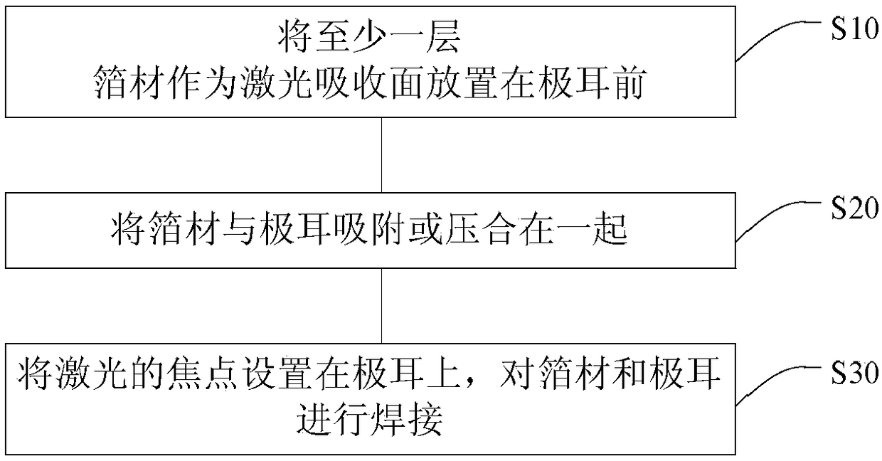
The invention discloses a method and device for laser-welding foil and a lug. The method comprises the following steps of taking at least one layer of the foil as a laser absorbing surface to put in front of the lug; adsorbing or pressing the foil and the lug together; arranging a laser focus on the lug; and welding the foil and the lug. The method adopts non-contact type laser welding to replaceconventional ultrasonic contact type welding, so that the foil and the lug are not affected by external force, and processing is stable. Laser processing efficiency is high, and multi-pulse light spots of laser can be adopted for process.

Description

technical field [0001] The invention relates to the field of lithium battery production, in particular to a method and device for laser welding foil and tabs. Background technique [0002] In the process of welding tabs of lithium-ion battery pole pieces and foils, the traditional welding method is ultrasonic welding, but ultrasonic welding of foils and tabs has several very difficult problems: serious virtual welding (it will also cause detachment after a long time) Welding phenomenon), too large penetration burrs, the tension between the foil and the lug cannot be guaranteed stably and effectively, the discharge current is not enough during the formation discharge process, and the resistance is too large, etc. These unavoidable technical problems will cause trouble to the subsequent process and have a great impact on the production and use of the entire battery. [0003] When the ultrasonic wave acts on the contact surface of the material, it will generate tens of thousan...

Claims


Application Information

Patent Timeline
Patent Type & Authority Applications(China)
IPC IPC(8): B23K26/21B23K26/70H01M50/531
CPCB23K26/21B23K26/702
Inventor 吴学科夏佳辉陈强阳如坤程志保
Owner SHENZHEN GEESUN INTELLIGENT TECHNOLOGY CO LTD
Learn More