Light combining module

Inactive Publication Date: 2019-04-11
YOUNG OPTICS
View PDF5 Cites 2 Cited by
  • Summary
  • Abstract
  • Description
  • Claims
  • Application Information

AI Technical Summary

Benefits of technology

The invention is a light combining module that uses an alignment structure to adjust the position of a light source module, a dichroic mirror, or a collimating lens to improve brightness performance. This results in higher brightness and better image quality for a projector. The alignment structure helps to change the position where the light is incident on the light source module, which enhances excitation efficiency. Essentially, this module produces higher brightness and good image quality for a projector.

Problems solved by technology

Consequently, how to further effectively excite the green LED has become an urgent issue that needs to be addressed in this field.

Method used


Image

  • Light combining module
  • Light combining module
  • Light combining module

Examples


Embodiment Construction

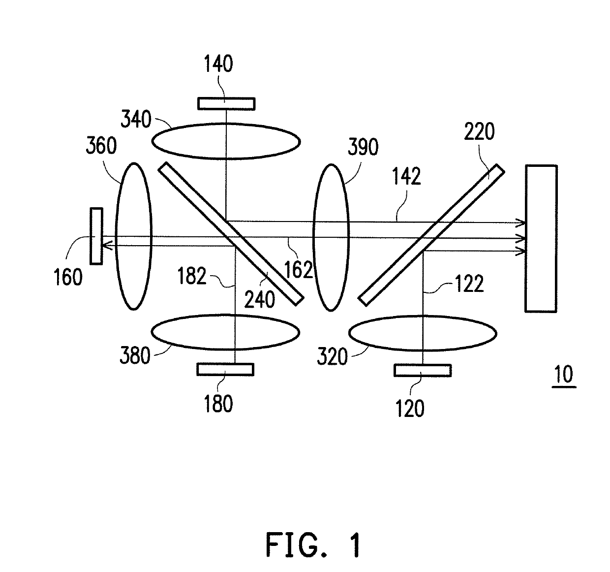
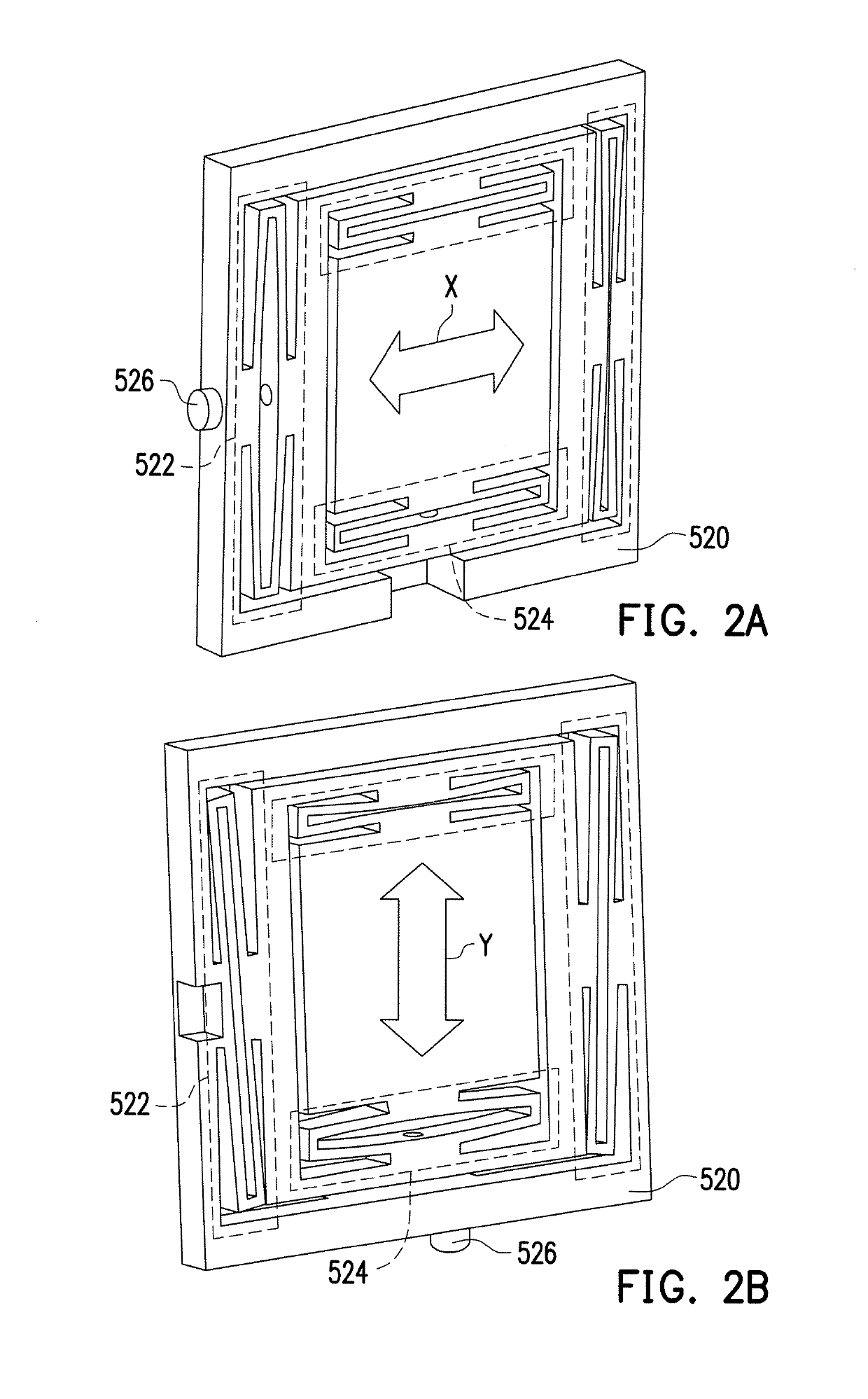
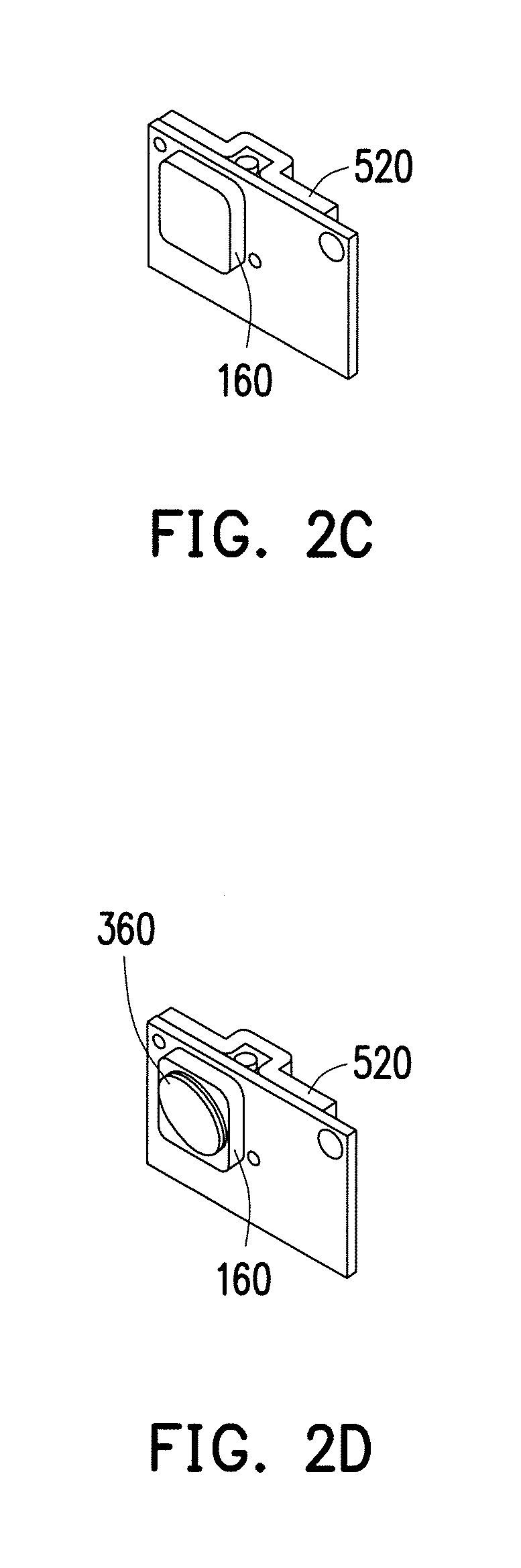
[0020]FIG. 1 is a schematic view of a light combining module according to an embodiment of the invention. FIG. 2A is a schematic view of an alignment structure according to an embodiment of the invention. FIG. 2B is a schematic view illustrating a fastening component of the alignment structure of FIG. 2A fastened in a Y direction. FIG. 2C is a schematic view illustrating the alignment structure of FIG. 2A assembled with the light source module of FIG. 1. FIG. 2D is a schematic view illustrating the alignment structure of FIG. 2A assembled with the light source module and collimating lens of FIG. 1. FIG. 2E is a schematic view illustrating the alignment structure of FIG. 2A assembled with a heat wink and with the light source module and collimating lens of FIG. 1.

[0021]With reference to FIG. 1 and FIG. 2A simultaneously, in this embodiment, a light combining module 10 includes a plurality of light source modules 120, 140, 160, and 180, a plurality of dichroic mirrors 220 and 240, a p...


PUM


Abstract

A light combining module includes a first light source, a second light source, a first dichroic mirror, and a first alignment structure. The first light source is used to output a first light. The second light source is used to output a second light. The first dichroic mirror is disposed on a transmission path of the first light and the second light, wherein the first light is incident on the second light source via the first dichroic mirror. The first alignment structure adjusts the position of the second light source.

Description

BACKGROUND OF THE INVENTIONField of the Invention[0001]The invention relates to a light combining module and particularly relates to a light combining module that has an alignment structure.Description of Related Art[0002]In conventional projection modules, a projection light is mostly generated by using a red light emitting diode (LED), a blue LED, and a green LED. The brightness of the image projected by the projection module depends on the brightness of the light output from the light source module thereof. Consequently, how to further effectively excite the green LED has become an urgent issue that needs to be addressed in this field.SUMMARY OF THE INVENTION[0003]The embodiments of the invention provide a light combining module that uses an alignment structure to adjust the position of a light source module, the position of a dichroic mirror, or the position of a collimating lens so as to enhance brightness performance of the light combining module. The light combining module th...

Claims


Application Information

Patent Timeline
IPC IPC(8): G03B21/20G02B27/14
CPCG03B21/2046G03B21/2013G03B21/2066G02B27/141G03B21/204G03B21/208G02B27/102G02B27/145
Inventor CHANG, YU-CHENYUN, CHI-CHUICHEN, YI-HSUEH
Owner YOUNG OPTICS
Why Eureka
Try Eureka