Shift device
A technology for shifting devices and gear components, which is used in transmission control, components with teeth, belts/chains/gears, etc., and can solve problems such as increasing the moving range.
- Summary
- Abstract
- Description
- Claims
- Application Information
AI Technical Summary
Problems solved by technology
Method used
Image

Examples
no. 1 approach
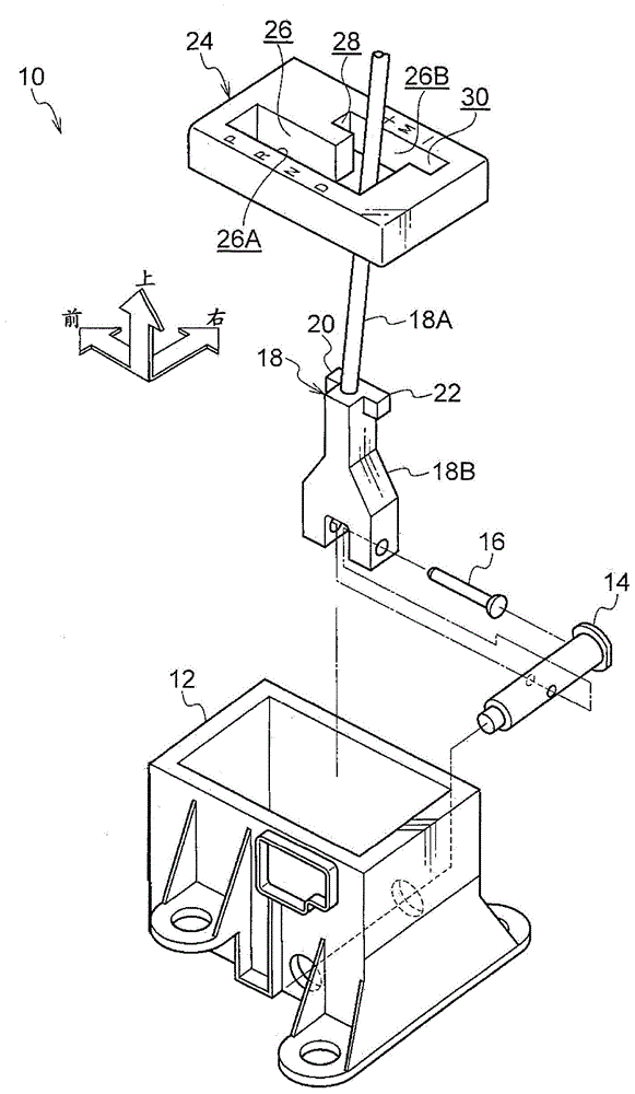
[0023] figure 1 The shift lever device 10 as the shift device according to the first embodiment of the present invention is shown in an exploded perspective view viewed obliquely from the left rear of the vehicle. In addition, in the drawings, the front of the vehicle is indicated by an arrow FR, the right side of the vehicle is indicated by an arrow RH, and the upward direction is indicated by an arrow UP.
[0024] The shift lever device 10 of the present embodiment is a so-called floor-type device, and is installed on a floor portion (floor) of a vehicle compartment which is a vehicle body side.
[0025] Such as figure 1 As shown, the shift lever device 10 includes a substantially rectangular parallelepiped box-shaped housing 12 as a support member, the housing 12 is fixed to the floor portion of the vehicle compartment, and has an open upper surface.
[0026] A circular shaft-shaped shift shaft 14 is provided at the lower end of the housing 12 as a first shaft. The shift ...
no. 2 approach
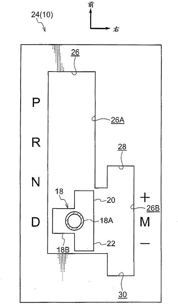
[0044] Figure 4 The strength gate 24 of the shift lever device 50 which is the shift device according to the second embodiment of the present invention is shown in a plan view seen from above.
[0045] The shift lever device 50 of this embodiment has almost the same structure as that of the above-mentioned first embodiment, but differs in the following points.
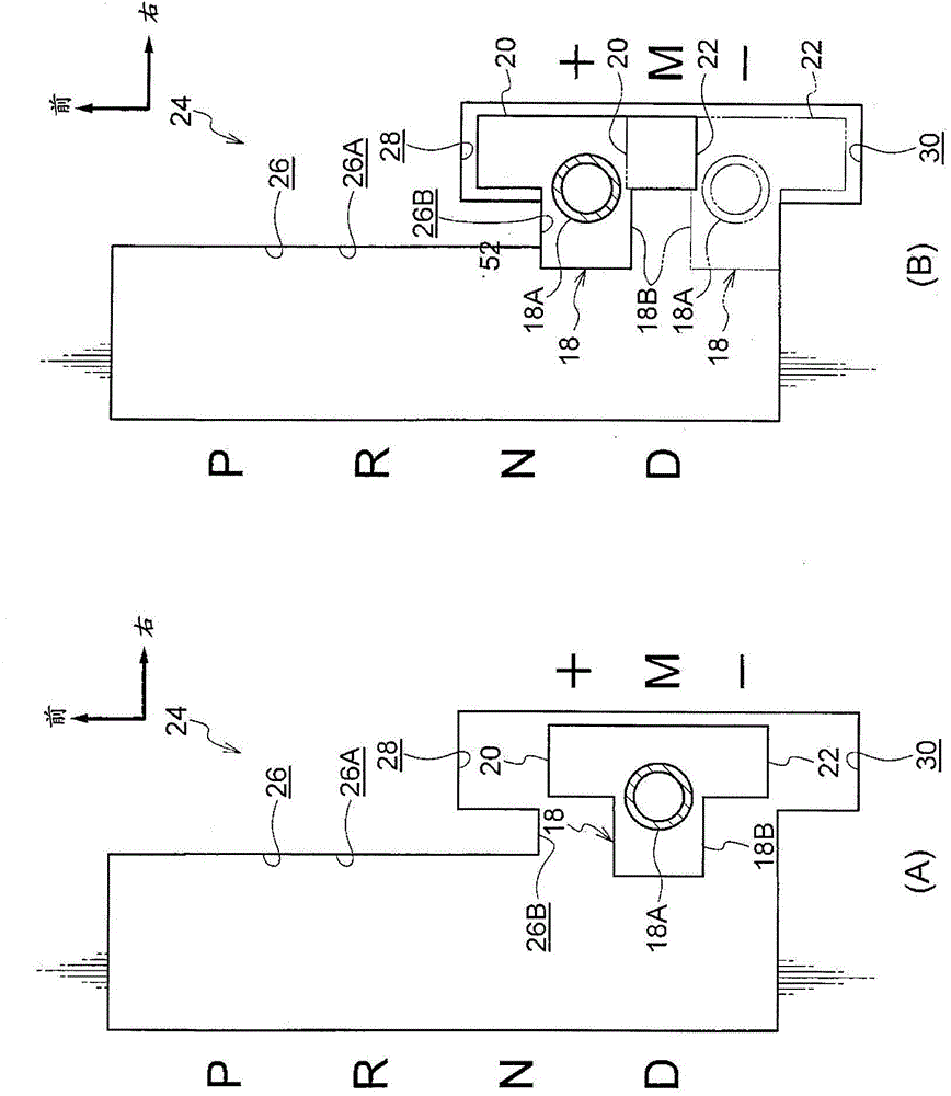
[0046] Such as Figure 4 As shown, in the shift lever device 50 of the present embodiment, on the first engaging portion 20 of the shift lever 18, a triangular columnar shape as a restricting portion is integrally provided at the vehicle front side end on the left side of the vehicle. The first protruding portion 52 protrudes from the first engaging portion 20 to the left side of the vehicle. The vehicle front side surface of the first protrusion 52 is a first inclined surface 52A serving as a guide portion, and the first inclined surface 52A is inclined in a direction toward the vehicle right side as it goes toward...
no. 3 approach
[0060] exist Figure 5 In the diagram, the strength gate 24 of the shift lever device 80 as the shift device according to the third embodiment of the present invention is shown in a plan view from above.
[0061] The shift lever device 80 of this embodiment has almost the same structure as that of the above-mentioned first embodiment, but differs in the following points.
[0062] Such as Figure 5 As shown, in the shift lever device 80 of the present embodiment, the first engaging portion 20 and the second engaging portion 22 of the shift lever 18 are made of metal (such as iron) and cylindrical, and the base ends are fitted into Molded and fixed to the support body 18B, the first engaging portion 20 and the second engaging portion 22 protrude from the support body 18B toward the vehicle front side and the vehicle rear side, respectively. The central axis of the first engaging portion 20 and the second engaging portion 22 are arranged on the right side of the vehicle with re...
PUM
 Abstract
Description
Claims
Application Information
 - R&D
- Intellectual Property
- Life Sciences
- Materials
- Tech Scout
- Unparalleled Data Quality
- Higher Quality Content
- 60% Fewer Hallucinations
Browse by: Latest US Patents, China's latest patents, Technical Efficacy Thesaurus, Application Domain, Technology Topic, Popular Technical Reports.
© 2025 PatSnap. All rights reserved.Legal|Privacy policy|Modern Slavery Act Transparency Statement|Sitemap|About US| Contact US: help@patsnap.com