
Continuous zooming infrared lens with extra large zoom ratio

A technology of infrared lens and zoom ratio, which is applied in the field of continuous zoom infrared lens, can solve the problems of few types of long-wave infrared materials, few applications of ultra-large zoom ratio lenses, and increase the difficulty of designing super-large zoom ratio continuous zoom infrared lenses. Achieve high light transmittance, which is conducive to the effect of large field of view target search

Active Publication Date: 2014-06-11
山东神戎电子股份有限公司
View PDF8 Cites 18 Cited by
  • Summary
  • Abstract
  • Description
  • Claims
  • Application Information

AI Technical Summary

Problems solved by technology

[0003] In the design of long-wave infrared zoom system, in order to pursue high transmittance and reduce cost (LWIR materials are very expensive), the number of lenses used is often reduced as much as possible, and at the same time, there are few types of LWIR materials, which increase the super large zoom ratio Difficulty in Designing Continuous Zoom Infrared Lens
[0004] In recent years, some uncooled infrared zoom lenses are more and more recognized by users, but the application of ultra-large zoom ratio lenses is still relatively small. The large zoom ratio zoom lens disclosed in Chinese patent document CN101482647B uses 6 lenses, and only realizes 5 3x, 6x or 7x zoom ratio, and the large zoom ratio lens disclosed in Chinese patent document 203385929U is only 6x. From the above description, we can see that the design of a super large zoom ratio lens is a huge problem. At present, there is no continuous zoom infrared lens that can produce clear images in a wide-angle state and can achieve a zoom ratio of 10 times or even higher

Method used


Image

  • Continuous zooming infrared lens with extra large zoom ratio
  • Continuous zooming infrared lens with extra large zoom ratio
  • Continuous zooming infrared lens with extra large zoom ratio

Examples


Embodiment Construction

[0029] The present invention will be further described below in conjunction with the accompanying drawings and embodiments.

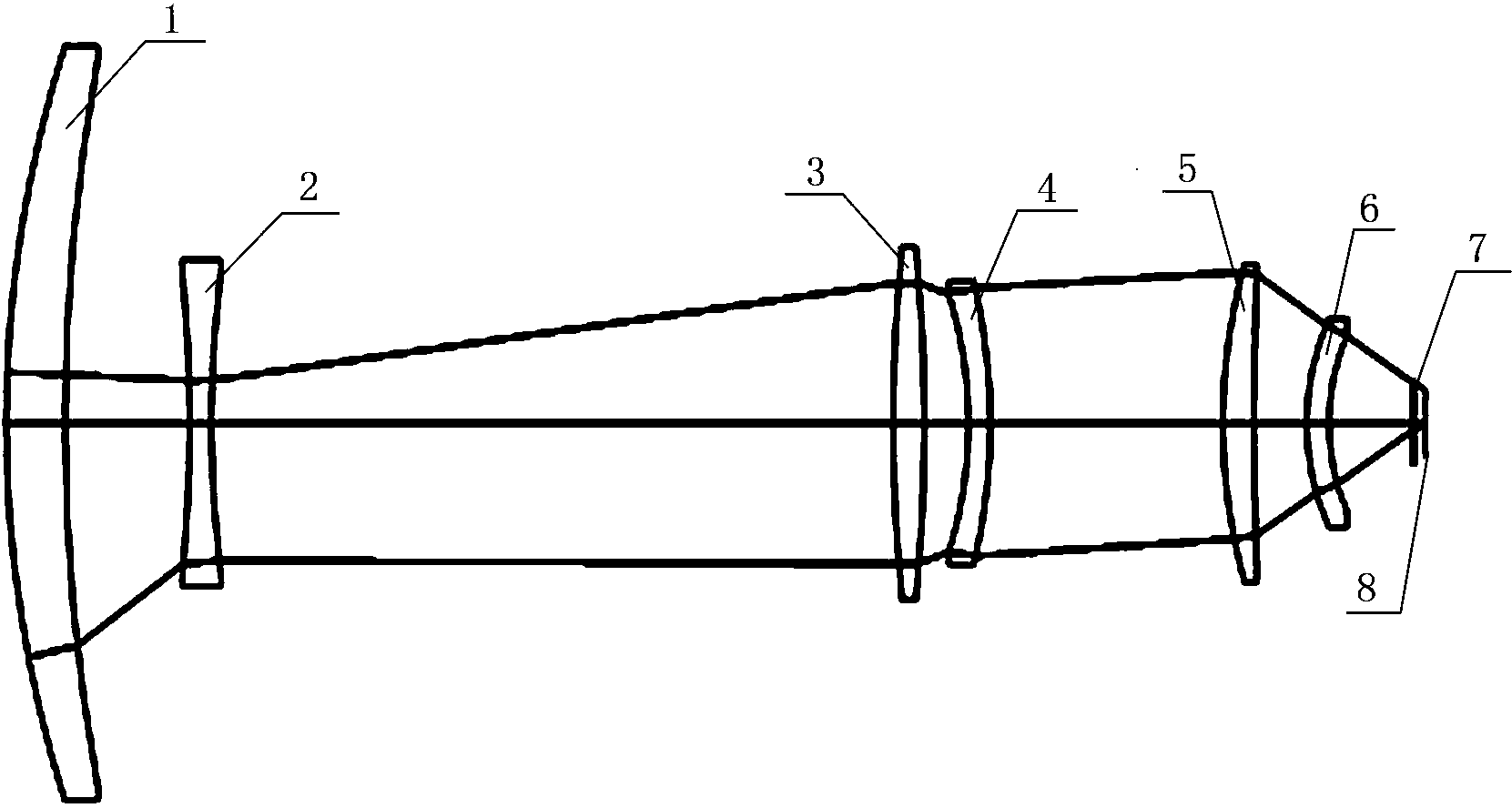
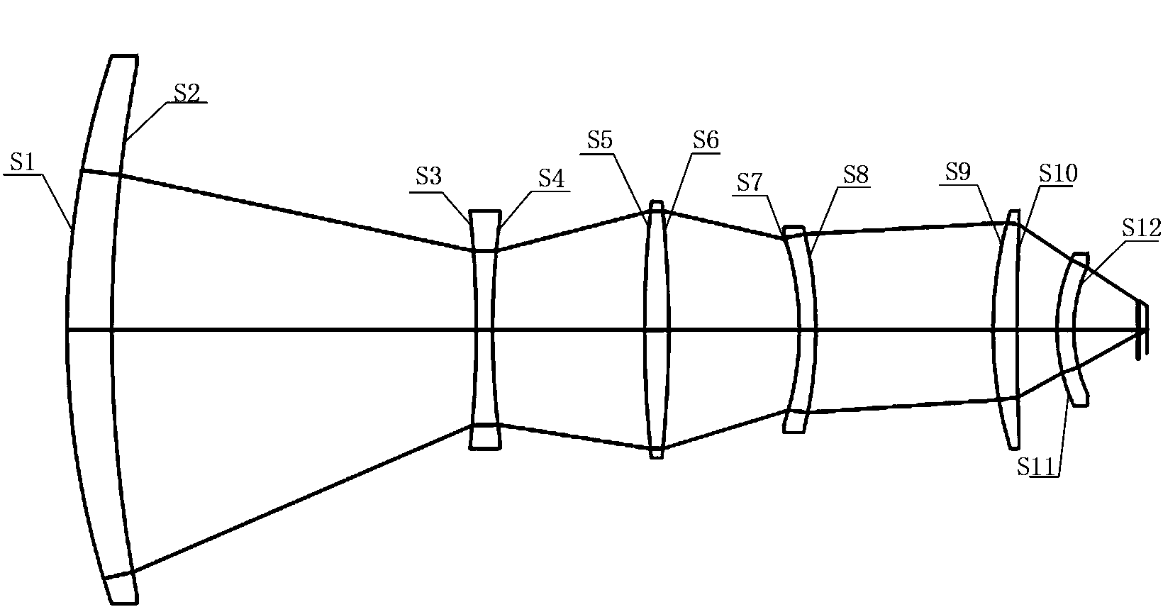
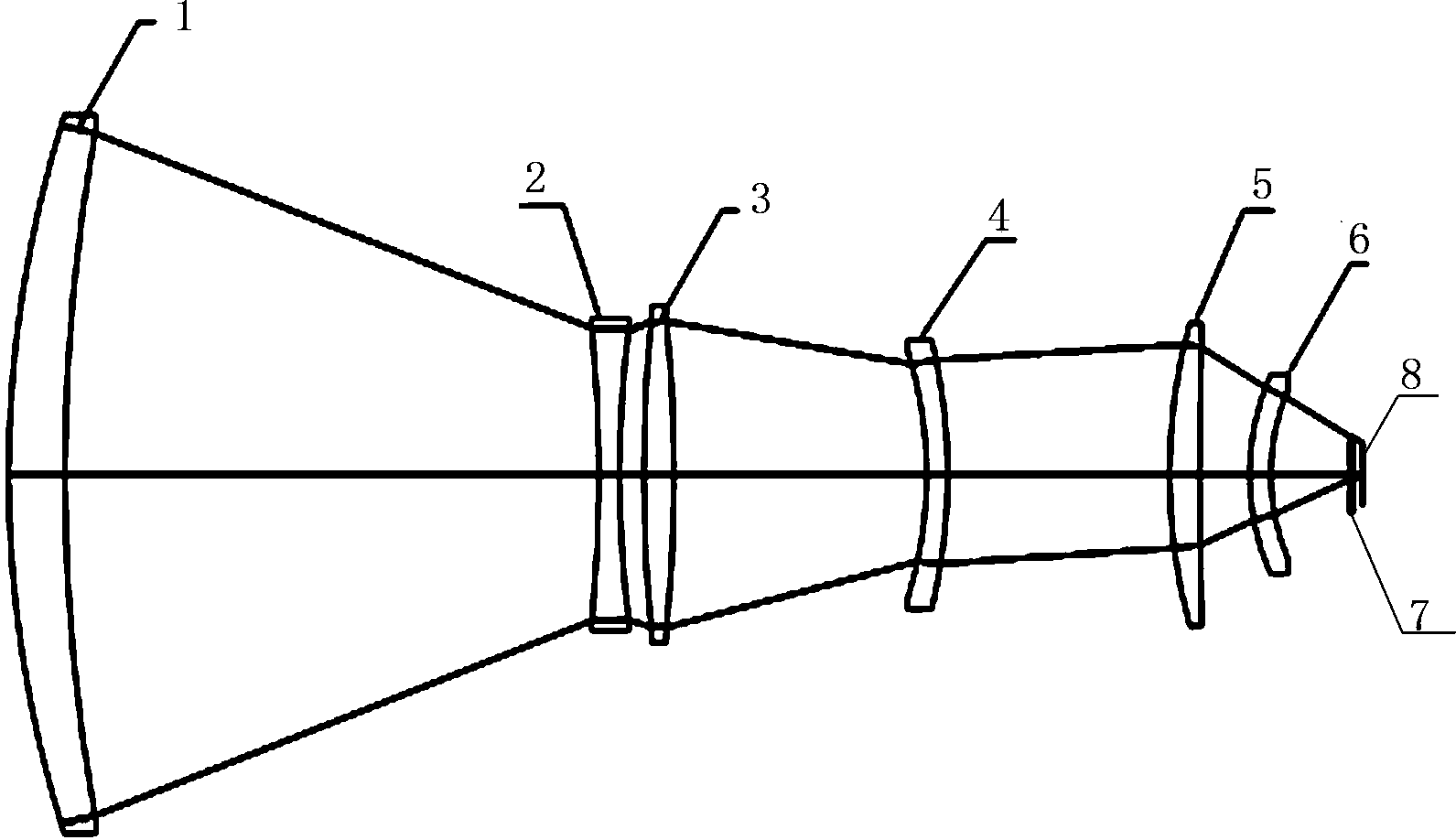
[0030] Such as figure 1 , figure 2 and image 3As shown, the structure schematic diagrams of the continuous zoom infrared lens of the present invention in the wide-angle, medium-focus and telephoto states are respectively provided, which include the front fixed group 1, the zoom group 2, the compensation group 3, and the first rear fixed group 4 , focusing group 5, second rear fixed group 6, detector window 7, and detector 8; the front fixed group 1 shown is composed of a positive meniscus lens, the convex surface of the positive meniscus lens faces the object side, and has positive diopter, Convergence of light is realized; the detector 8 converts the received light signal into an electrical signal. Zoom group 2, compensation group 3, first rear fixed group 4, focusing group 5, second rear fixed group 6, and detector window 7 are sequentially arran...


PUM


Abstract

The invention relates to a continuous zooming infrared lens with an extra large zoom ratio. The continuous zooming infrared lens with the extra large zoom ratio is sequentially provided with a front fixing set, a zoom set, a compensation set, a first rear fixing set, a focusing set and a second rear fixing set along an optical axis from the object side, the zoom set and the compensation set are a biconcave negative lens and a biconvex positive lens respectively, the first rear fixing set is a negative meniscus lens, and the focusing set and the second rear fixing set are respectively a positive meniscus lens. The six lens have the positive diopter, the negative diopter, the positive diopter, the negative diopter, the positive diopter and the positive diopter respectively. When the lens changes from the wide angle state to the long focus state, the distance from the zoom set to the front fixing set and the distance from the compensation set to the first rear fixing set increase gradually. The infrared lens can achieve the ultra large zoom ratio of ten times or more. Because only the six lens are adopted, the light transmittance is guaranteed; the infrared lens is compact in structure and easy to install, adjust and assemble and has the temperature compensation function.

Description

technical field [0001] The present invention relates to a super-large zoom ratio continuous zoom infrared lens, more specifically, to a continuous zoom infrared lens with a super large zoom ratio by rationally selecting and arranging different types of lenses. Background technique [0002] Due to the advantages of small size and light weight, uncooled thermal imaging cameras have developed rapidly in recent years. The focal length of the infrared zoom thermal imager can be changed continuously, that is, it can monitor a large area, and can zoom in on the target for careful observation. During the zooming process, the target information will not be lost, so that the uncooled infrared zoom thermal imager can be used in security monitoring, forest fire prevention, and safety monitoring. It has been widely used in production and other fields. [0003] In the design of long-wave infrared zoom system, in order to pursue high transmittance and reduce cost (LWIR materials are very ...

Claims


Application Information

Patent Timeline
IPC IPC(8): G02B15/173
Inventor 刘涛徐玉惠陈大明
Owner 山东神戎电子股份有限公司
Learn More