Method of performing tomographic imaging of sample in charged-particle microscope

A charged particle microscope and charged particle technology, applied in the field of tomography, can solve problems such as image resolution disappointment, and achieve the effect of reducing size and improving SNR

Active Publication Date: 2014-06-11
FEI CO
View PDF4 Cites 11 Cited by
  • Summary
  • Abstract
  • Description
  • Claims
  • Application Information

AI Technical Summary

Problems solved by technology

However, while this approach successfully produces a 3D (synthetic) image of the specimen, the resolution of this image has so far generally proven to be rather disappointing

Method used


Image

  • Method of performing tomographic imaging of sample in charged-particle microscope
  • Method of performing tomographic imaging of sample in charged-particle microscope
  • Method of performing tomographic imaging of sample in charged-particle microscope

Examples


Embodiment 1

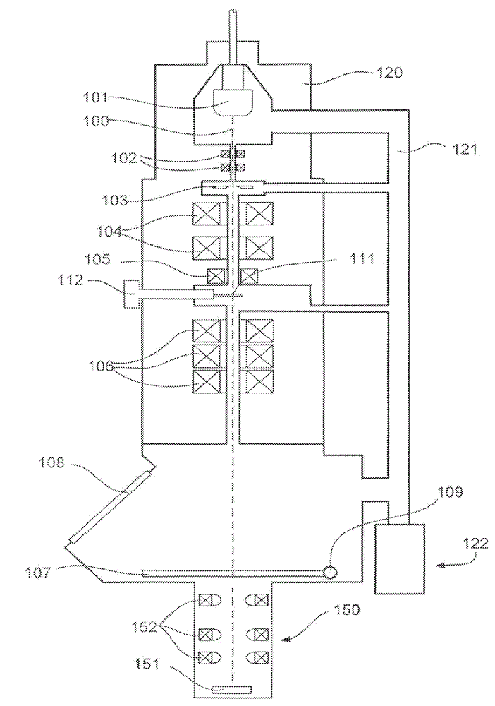
[0077] figure 1 A highly schematic longitudinal cross-sectional view showing a particular embodiment of a CPM in which the invention may be applied. In this case, the CPM is TEM.

[0078] The depicted TEM includes a vacuum housing 120 that is evacuated via a tube 121 connected to a vacuum pump 122 . A particle source in the form of an electron gun 101 generates an electron beam along an optical axis (imaging axis) 100 of the particles. For example, the electron source 101 can be a field emission gun, a Schottky emitter or a thermionic emitter. Electrons generated by source 101 are accelerated to an adjustable energy of typically 80 keV to 300 keV (but TEMs using electrons with adjustable energy of eg 50 keV to 500 keV are also known). Next, the accelerated electron beam passes through a beam confining aperture / aperture 103 provided in the platinum plate. In order to properly align the electron beam with aperture 103 , the beam can be diverted and tilted by means of deflec...

Embodiment 2

[0092] Figure 2 shows the results of TEM imaging on biological samples. More specifically, these figures are used to illustrate the effect of different focus settings when imaging tilted samples. In each case, the plane (page) of a given figure can be considered to be the focal plane (FP) of the particle optics column used to image the sample onto the detector.

[0093] exist Figure 2A , the sample is posed such that its surface S (the distal side of the sample holder it rests on) is parallel to FP. Therefore, all points on S are basically in focus.

[0094] exist Figure 2B In , the same sample is tilted in such a way that S subtends the angle it makes with FP. As depicted here, the left region of the FP is intersected by the S so that this portion of the sample is in focus. The rest of the S is below (or above) the FP, and is thus out of focus, whereby one looks towards Figure 2B Steadily increasing blur as you move to the right of .

[0095] exist Figure 2C , the...


PUM


Abstract

A method of performing tomographic imaging of a sample in a charged-particle microscope is disclosed. The method comprises the following steps: providing a beam of charged particles that propagate along a particle-optical axis; disposing the sample on a sample holder that can be tilted relative to the beam; in an imaging step, directing the beam through the sample so as to form and capture an image of the sample at an image detector; repeating the procedure at each of a series of sample tilts so as to acquire a corresponding set of images; and in a reconstruction step, mathematically processing images from the set so as to construct a composite image of the sample, and therefore, in the imaging step, a sequence of component images is captured at a corresponding sequence of focus settings. In the reconstruction step, for at least one member of the series of sample tilts, a plurality of members of the sequence of component images are used in the mathematical image processing. Accordingly, a 3D imaging cube rather than a 2D imaging sheet at a given sample tilt is obtained.

Description

technical field [0001] The invention relates to a method for performing tomography of a sample in a charged particle microscope comprising the steps of: [0002] providing a beam of charged particles propagating along the optical axis of the particles; [0003] positioning the sample on a sample holder that is tiltable with respect to the beam; [0004] during the imaging step, directing the beam through the sample to form and capture an image of the sample at the image detector; [0005] This procedure is repeated for each of the column sample tilts in order to obtain a corresponding set of images; [0006] In a reconstruction step, images from the set are processed mathematically in order to construct a composite image of the sample. [0007] The invention also relates to a charged particle microscope comprising: [0008] a charged particle source for generating a beam of charged particles propagating along the optical axis of the particles; [0009] a sample holder for...

Claims


Application Information

Patent Timeline
Patent Type & Authority Applications(China)
IPC IPC(8): H01J37/26H01J37/28
CPCG01N23/2251G01N2223/418H01J2237/21H01J37/21H01J37/22G01N23/046H01J37/26H01J37/222H01J2237/226H01J2237/2802G01N2223/419
Inventor R.肖恩马克斯U.鲁伊肯E.M.弗兰肯
Owner FEI CO
Why Eureka
Try Eureka